 Diagram UTM - Switch - VLANs
Warnung: Der Anzeigetitel „VLAN Switch“ überschreibt den früheren Anzeigetitel „VLAN-Switch“.
Configuration of two logically separated VLANs on one switch
Last adaption: 12.2
New:
notemptyThis article refers to a Resellerpreview
11.7
Introduction
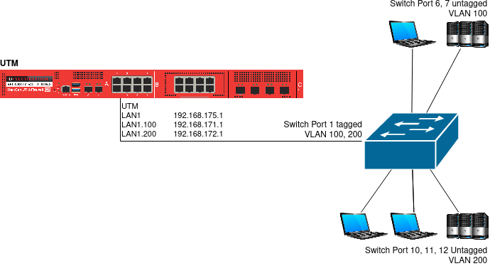
This section uses the example of a Netgear switch and a UTM to explain how to configure two logically separated VLANs.
Configure switch
|
- To configure the switch for VLAN, its web interface must be called up.
- There you will find the option "Add new VLAN" under the menu item "VLAN".
- Here the VLAN ID "100" is created and the ports are determined, which should belong to the VLAN 100.
- So that VLAN packets can be sent to the UTM, port 1 is set as a member of VLAN 100.
From now on, this provides outgoing packets from it with a VLAN tag.
- Ports 6 and 7 are also members, but outgoing packets are not tagged here.
|
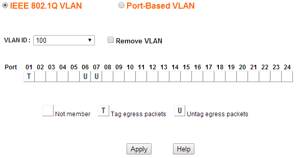 VLAN 100
|
- The VLAN 200 is set up in a similar way.
- Port 1 to the UMT is also tagged.
- The ports on which only devices from the VLAN are connected are not tagged.
|
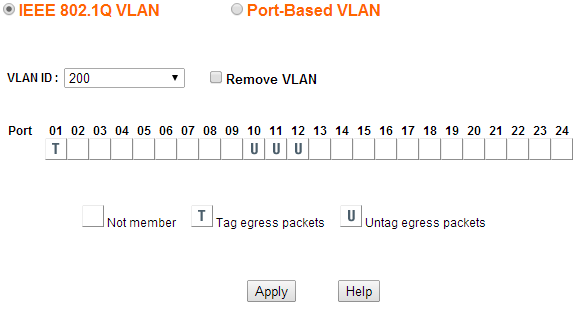 VLAN 200
|
- Under PVID Setting you define which ports should tag incoming packets.
- Here, packets arriving on ports 6 and 7 are tagged with VLAN ID 100.
- Ports 10, 11 and 12 are tagged with the VLAN ID 200.
|
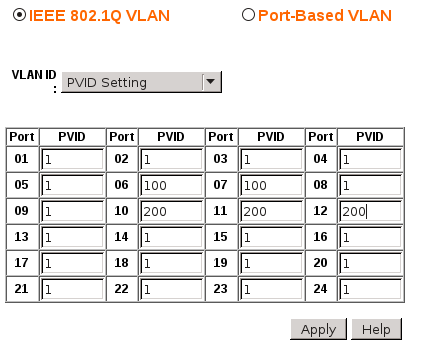 PVID settings
|
Configure UTM
In order to set up the UTM, two VLAN interfaces are required, on each of which two zones are bound.
|
Create VLAN interface
|
The creation of a VLAN interface is done under by pressing the VLAN button.
Further details in the article on Creating a VLAN interface
Since two VLANs are required here, this process must be done
- once with VLAN ID 100
- and another time with VLAN ID 200.
|
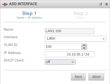 VLAN Creation Wizard (Step 1)
|
The network configuration should now look like this: 
|


