notempty
notempty
notempty Dieser Artikel bezieht sich auf eine nicht mehr aktuelle Version!
notempty
Der Artikel für die neueste Version steht hier
Zu diesem Artikel gibt es bereits eine neuere Version, die sich allerdings auf eine Reseller-Preview bezieht
Create and configure a VLAN interface
Last adaptation to the version: 12.1
- New:
- Layout adjustment
Previous versions: 11.7
Creating a VLAN interface
The creation of a Vlan interface is done under Tab Network interfaces by pressing the button.
| Caption | Value | Description | |
|---|---|---|---|
Wizard step 1 (name and IP address) | |||
| Name: | LAN1.100 | The name of the virtual interface is automatically formed from the physical interface used and the VLAN ID | 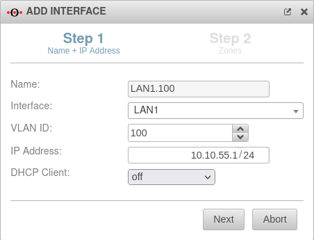 |
| Interface: | LAN1 | physical interface used | |
| VLAN ID | 100 | VLAN ID used (here:100) | |
| IP address: | 10.10.55.1/24 | IP address of the virtual interface | |
| DHCP Client | off | When activated, the interface obtains its IP address as a client from a DHCP server. | |
Wizard Step 2 (Zones) | |||
| Zones | Under the menu item Zones, the zones of the interface are displayed or defined. For a better understanding there is a corresponding article Zone concept in the Wiki. |
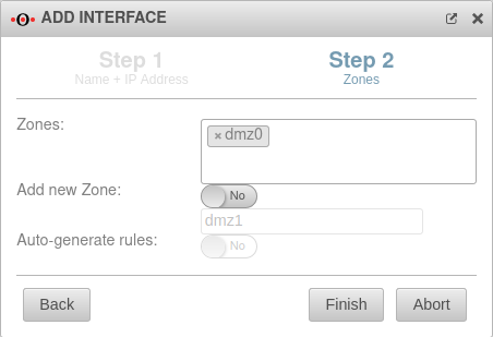 | |
| Add new zone | Yes | Automatically adds a new zone and associates it with the virtual interface. The associated zone for the interface itself (firewall-) is automatically generated and does not need to be specified. | |
| dmz0 | Name for the new zone | ||
| Generate rules: | No | Creates autogenerated rules to facilitate commissioning. These rules cannot be changed and must be replaced by individual rules in any case. | |
| Complete the wizard with | |||
| The resulting VLAN configuration might look like the following: | |||
Edit VLAN interface | |||
General General
| |||
| Name: | LAN1.100 | The name of the virtual interface is automatically formed from the physical interface used and the VLAN ID | 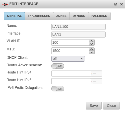 |
| Interface: | LAN! | physical interface used | |
| VLAN ID | 100 | VLAN ID used (here:100) | |
| MTU | 1500 | The Maximum Transmission Unit specifies the maximum packet size in bytes that can be transmitted without fragmentation. | |
| DHCP Client | off | When activated, the interface obtains its IP address as a client from a DHCP server. | |
| Router Advertisement: | Off | Routers announce their presence in the network via Router Advertisement(RA). This happens periodically or on Router Solicitation requests (RS-Request). If the UTM has received an IPv6 prefix, it can announce the subnet via Router Advertisement in the network segment behind the interface. (See article IPv6 Prefix Delegation) | |
| Route Hint IPv4 | Via the field "Route Hint" it is possible to define the gateway of the interface. This has the advantage, for example, that only the interface (e.g. LAN3) has to be specified in routing and not directly the gateway IP. | ||
| Route Hint IPv6 | Via the field "Route Hint" it is possible to define the gateway of the interface. This has the advantage, for example, that only the interface (e.g. LAN3) has to be specified in routing and not directly the gateway IP. | ||
| IPv6 Prefix Delegation | Off | Enables IPv6 prefix delegation to get IPv6 prefixes allocated on this interface. | |
IP addresses IP addresses
| |||
| IP addresses: | » ✕10.10.55.1/24 | By clicking in the click box, one or more addresses can be placed on an interface. | 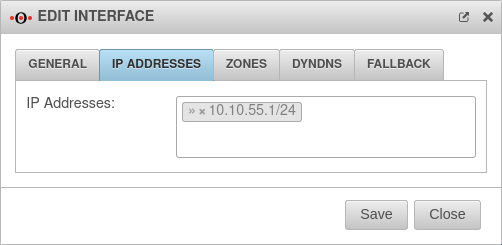 |
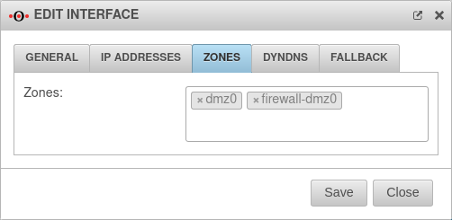
ZonesZones
| |||
| Zones | » ✕dmz0 » ✕firewall-dmz0 | Under the menu item Zones, the zones of the interface are displayed or defined. For a better understanding there is a corresponding article Zone concept in the Wiki. |
 |
DynDNSDynDNS
| |||
| Enabled: | Yes | Enables or disables (default) the DynDNS function | 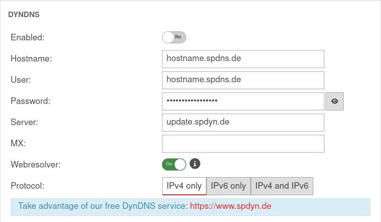 |
| Hostname: | hostname.spdns.de | Desired Hostname | |
| User: | hostname.spdns.de | The corresponding user name must be entered here. | |
| Password: | The password must be entered here. | ||
| Server: | update.spdyn.de | The securepoint update server | |
| MX: | |||
| Webresolver: | On | Must be activated if the NAT router is located before the DNS (i.e.: UTM → Fritzbox/Speedport → internet) | |
| Protocol: | The DNS service can be activated for IPv4 or IPv6 addresses only, or both IPv4 and IPv6. | ||
FallbackFallback
| |||
| Fallback interface | Interface that takes over for the main interface in the event of a malfunction. The absence of malfunctions is checked by ping-checking a host. See the separate article on Fallback for this. |
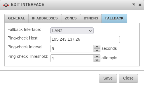 | |
| Ping-check Host | 195.243.137.26 | Host on which the ping check should be performed. This can also be a host in the internal network if necessary. (Here the DNS servers of DENIC in Hamburg and Munich). | |
| Ping-check Intervall | 5 | Period between ping attempts | |
| Ping-check Threshold | 4 Attempts | Number of failed ping attempts before switching to the fallback interface. | |