Jump to:navigation, search
Wiki


De.png
En.png
Fr.png


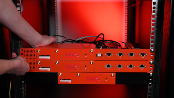
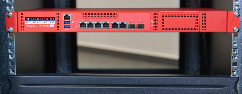
Instructions for installing a Securepoint UTM G5 in a server rack.
Last adaption: 12.2021
New:
  • Installation instructions for the Basic Kit for the RC100
  • Installation instructions for the Premium Kit for the RC100
  • Installation instructions for the Premium Kit for the RC200
  • Video tutorial
notempty
This article refers to a Resellerpreview

G3/G4


Specification


Hint
  • For reliable operation of our hardware throughout its life cycle, it must be operated within its specifications:
    • The maximum ambient temperature for operation is 40°C
    • The minimum ambient temperature for operation is 0°C
    • Relative humidity must be between 10% and 80% and condensation must be prevent
  • For installation, make sure that the firewall is mounted/set up as follows:
    • Sufficient supply of cool air
    • The device must not be covered
    • The device must be as free-standing as possible
  • When mounting in a network rack, special attention must be paid to:
    • The rack must be ventilated
    • Passively cooled devices (Black Dwarf G3+G5, RC100 G3, RC200 G3) must not be placed directly below or above heat emitting devices.
    • There must be no build-up of heat


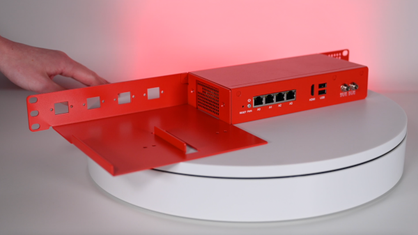
RC100 Basic Kit

Basic kit 2.png
Fig. 1
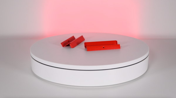
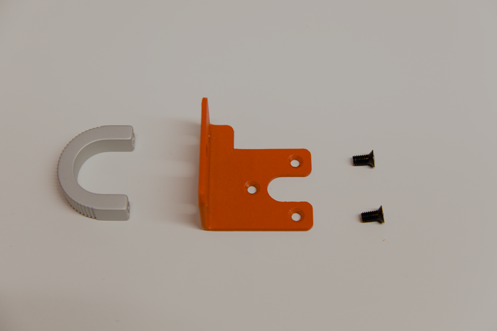
Step 1
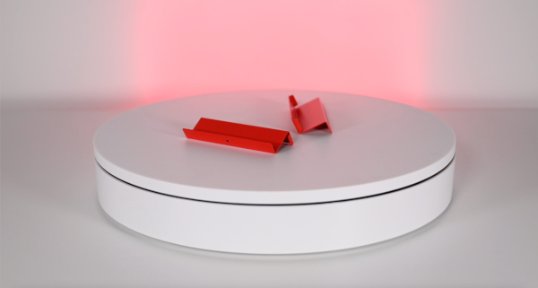
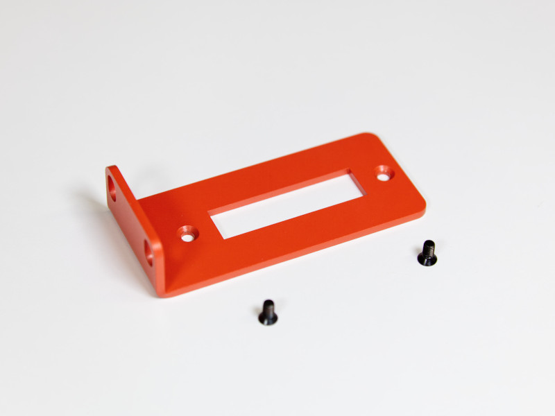
  • Mounting bracket for the sides
Basic kit 4.png
Fig. 2
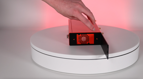
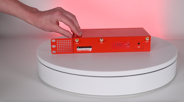
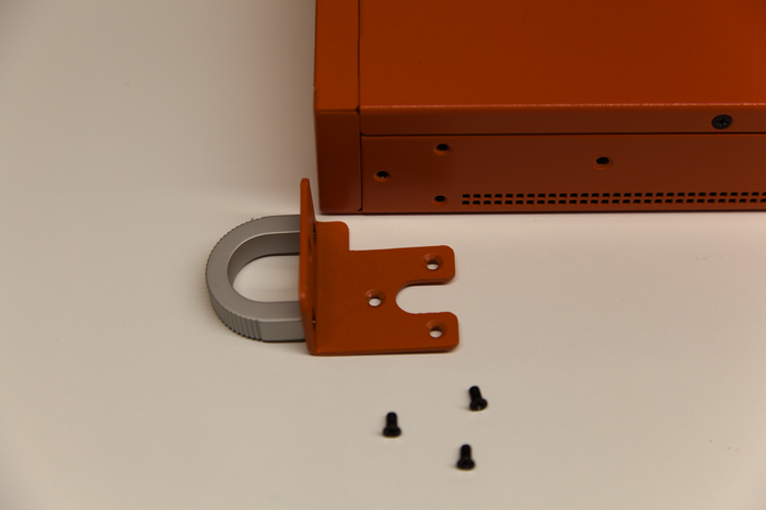
Step 2
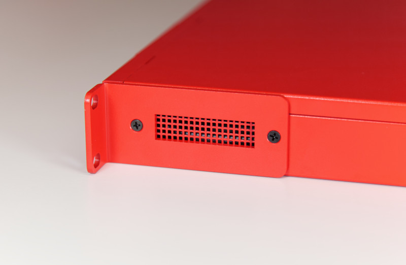
  • Mounting bracket leaves ventilation outlet free
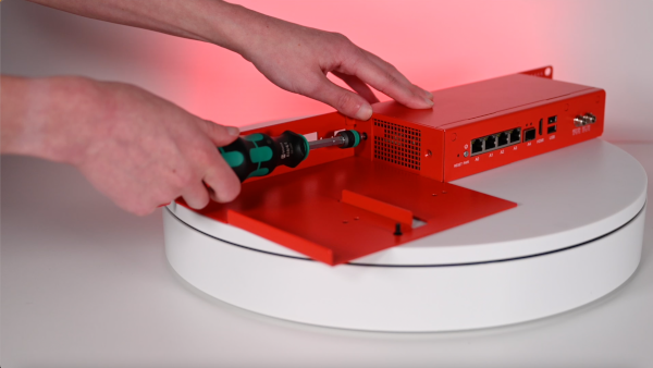
Basic kit 5.png
Fig. 3
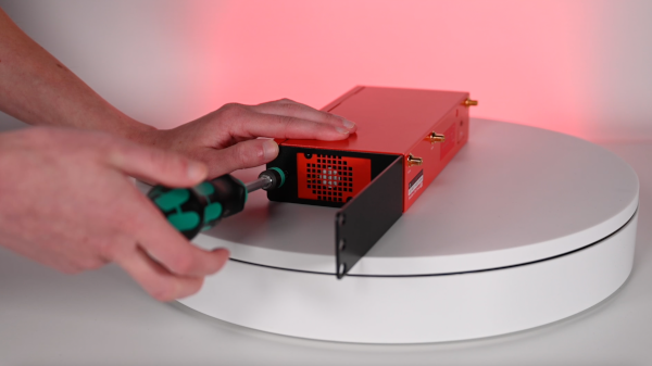
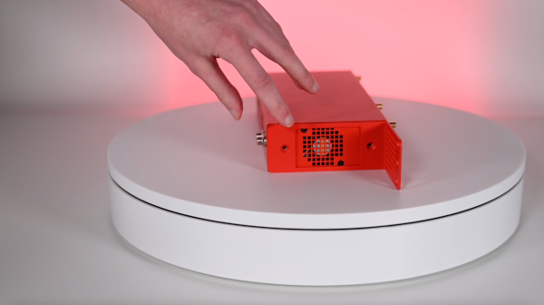
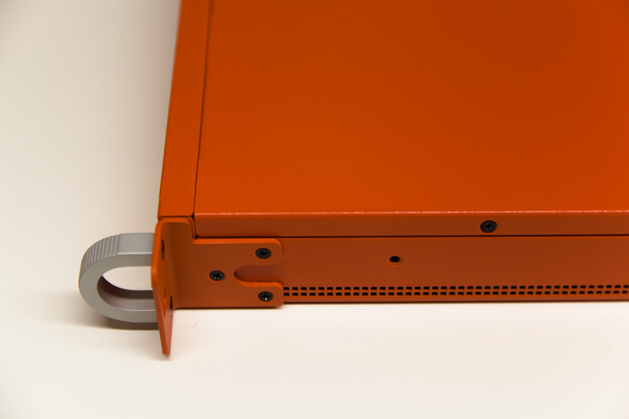
Step 3
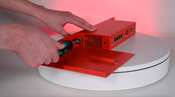
  • Fasten mounting bracket laterally
Basic kit 6.png
Fig. 4
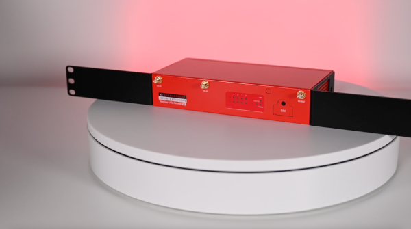
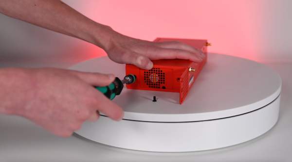
Step 4
  • Fasten mounting bracket on the second side
Basic kit 7.png
Fig. 5
Step 5
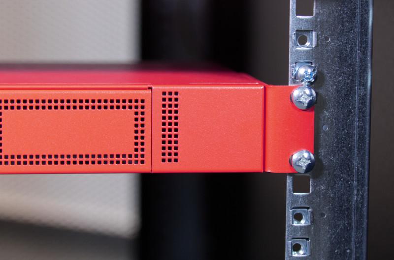
  • Space requirement in server rack: 1U
Basic kit 8.png
Fig. 6
Step 6
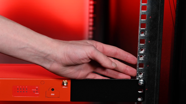
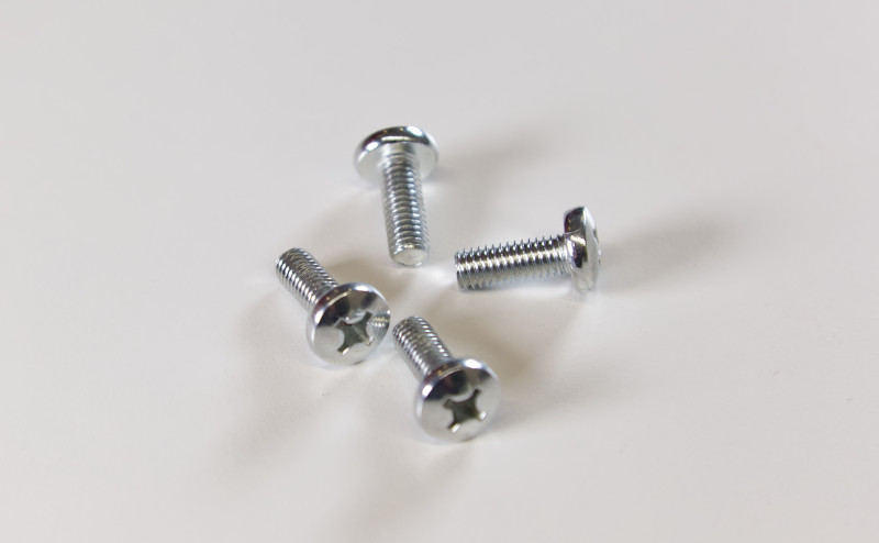
  • Attach mounting bracket to the rack with the large silver screws
    Done


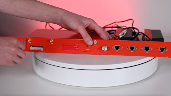
RC100 Premium Kit

Rc100 pro kit 2.png
Fig. 1
Step 1
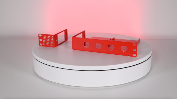
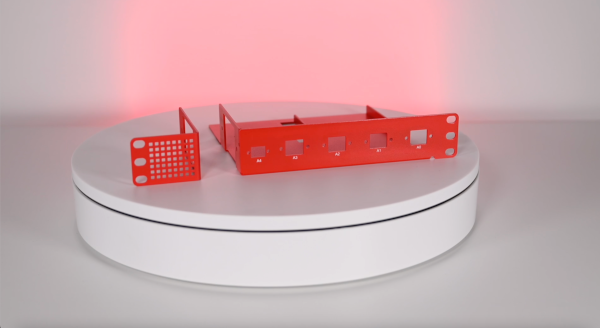
  • Mounting bracket left (narrow) and right (wide)
Rc100 pro kit 3.png
Fig. 2
Step 2
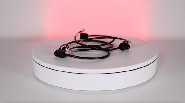
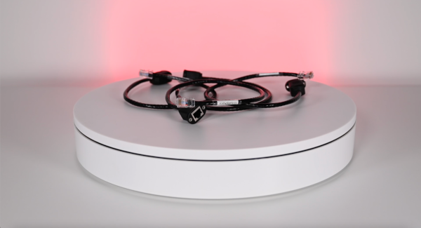
  • supplied patch cable
Rc100 pro kit 4.png
Fig. 3
Step 3
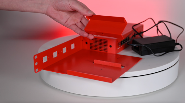
  • Mounting bracket for power supply unit(s)
Rc100 pro kit 5.png
Fig. 4
Step 4
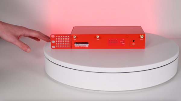
  • The narrow mounting bracket goes on the left side of the UTM
Rc100 pro kit 6.png
Fig. 5
Step 5
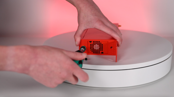
  • The ventilation outlet remains free
Rc100 pro kit 7.png
Fig. 6
Step 6
  • Mounting with two black screws
Rc100 pro kit 8.png
Fig. 7
Step 7
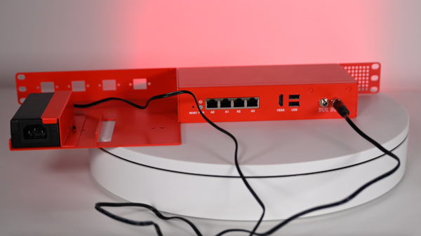
  • The wide mounting bracket with the power supply and network connections is mounted on the right side.
Rc100 pro kit 9.png
Fig. 8
Step 8
  • Fastening again with two black screws
Rc100 pro kit 11.png
Fig. 9
Step 9
  • Mounting bracket for the power supply unit
Rc100 pro kit 12.png
Fig. 10
Step 10
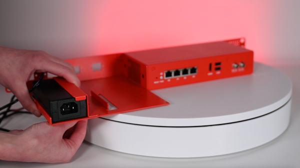
  • Screw the mounting bracket tight from below
Rc100 pro kit 13.png
Fig. 11
Step 11
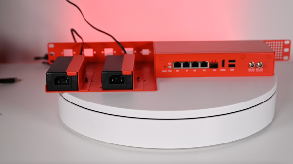
  • Attached power supply with connection to the UTM.
  • The cable should be neatly routed later
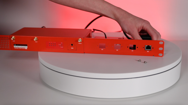
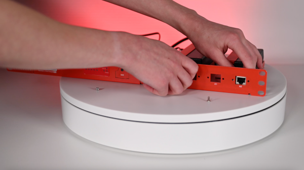
Rc100 pro kit 14.png
Fig. 12
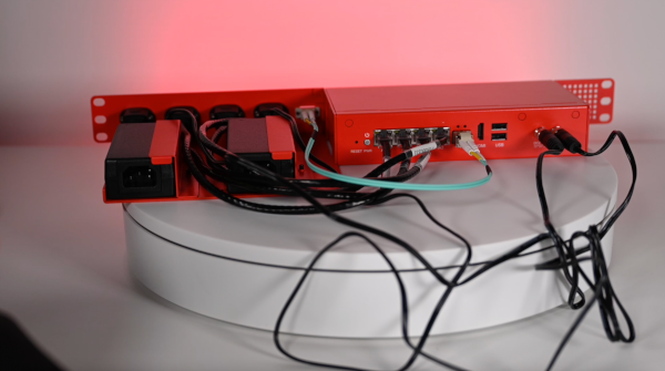
Step 12
  • Plug in the patch cable at the back
  • and fasten at the front at the correspondingly labeled opening with the silver screws
  • Inverse running direction of the label!
    The label follows the arrangement of the status lights on the front side of the UTM
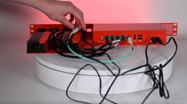
  • Rc100 pro kit 15.png
    Fig. 13
    Step 13
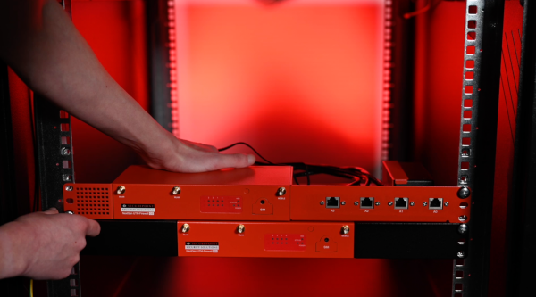
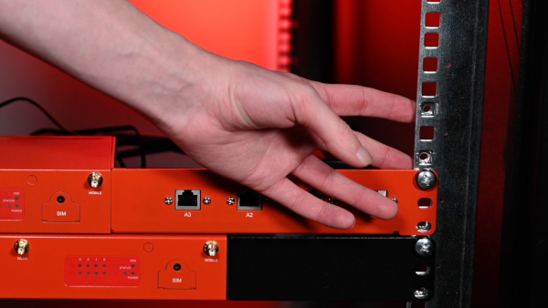
    • The UTM requires 1U
    Rc100 pro kit 16.png
    Fig. 14
    Step 14
    • Screwing with the large silver screws
    • in the picture above


    RC200 Premium Kit

    Rc200 pro kit 2.png
    Fig. 1
    Step 1
    • Mounting bracket left (narrow) and right (wide)
    Rc200 pro kit 3.png
    Fig. 2
    Step 2
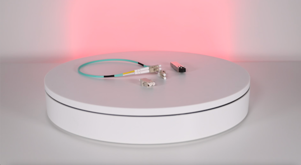
    • Included LC fiber optic cable
    Rc200 pro kit 4.png
    Fig. 3
    Step 3
    • Included LC fiber optic cable
    Rc200 pro kit 5.png
    Fig. 4
    Step 4
    • Mounting bracket for 2 power supplies
    Rc200 pro kit 6.png
    Fig. 5
    Step 5
    • The narrow mounting bracket goes on the left side of the UTM
    Rc200 pro kit 7.png
    Fig. 6
    Step 6
    • Mounting with two black screws
    Rc200 pro kit 10.png
    Fig. 7
    Step 7
    • The wide mounting bracket with the power supply and network connections is mounted on the right side.
    • Mounting also with two black screws
    Rc200 pro kit 13.png
    Fig. 8
    Step 8
    • Screw down the mounting bracket for the power supply units from below
    Rc200 pro kit 15.png
    Fig. 9
    Step 9
    • Plug in the patch cable at the back
    • and fasten at the front at the correspondingly labeled opening with the silver screws
  • Inverse running direction of the label!
    The label follows the arrangement of the status lights on the front side of the UTM
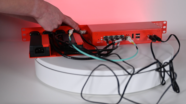
  • Rc200 pro kit 16.png
    Fig. 10
    Step 10
    • Plug the supplied SFP module into port A4 on the UTM and plug in the supplied LC fiber cable.
    Rc200 pro kit 18.png
    Fig. 11
    Step 11
    • Push through the connector for the SFP port from the inside with the long end facing outward
    Rc200 pro kit 19.png
    Fig. 12
    Step 12
    • Fastening the connector for the LC fiber optic cable
    Rc200 pro kit 21.png
    Fig. 13
    Step 13
    • Insert the LC fiber optic cable into the connector
    Rc200 pro kit 22.png
    Fig. 14
    Step 14
    • The UTM requires 1U
    Rc200 pro kit 23.png
    Fig. 15
    Step 15
    • Screwing with the large silver screws
    • in the picture above


    RC300S


    Preparation

    • Screwdriver type Ph2 (not enclosed).
    • Screws supplied:
      • 4 small black screws (M2x4 countersunk head)
      • 4 large silver screws (M5x15 flat head)


    Instructions

    Rackmounting-RC300S-1.jpg
    Fig. 1
    Step 1
    • Mounting bracket for the sides
    Rackmounting-RC300S-2.jpg
    Fig. 2
    Step 2
    • Attach mounting bracket to the side
    Rackmounting-RC300S-3.jpg
    Fig. 3
    Step 3
    • Screws to hold the mounting brackets in the rack
    Rackmounting-RC300S-4.jpg
    Fig. 4
    Step 4
    • Two screws each hold the mounting brackets in the rack
    Rackmounting-RC300S-5.jpg
    Fig. 5
    Step 5
  • Ready


  • Mounting RC300S in rack


    RC350R - RC1000R


    Preparation

    • Screwdriver type Ph2 (not enclosed)
    • Premium mounting rails
    • From the enclosed screw sets:
      • 4 thick black screws (M2x4 countersunk head)
      • 6 smaller black screws (M1x2 countersunk head)
      • 4 small silver-coloured screws (M4x4 flat head)
      • 2 large silver-coloured screws (M5x15 flat head)
      • 2 large silver-coloured screws with spacer (M5x15 flat head with shoulder)

    Instructions
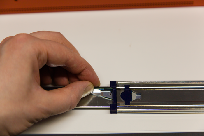
    RC350 Rackmounting 01.png
    Fig. 1
    Step 1
    • Components of a mounting bracket
    RC350 Rackmounting 02.png
    Fig. 2
    Step 2
    • Assemble the mounting brackets with the larger black screws
    RC350 Rackmounting 03.png
    Fig. 3
    Step 3
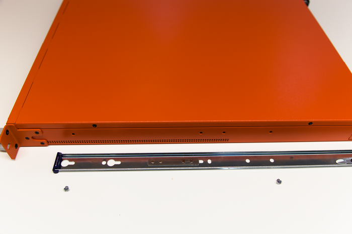
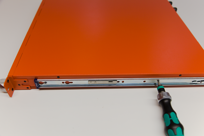
    • Attach the mounting bracket to the enclosure with the smaller black screws
    RC350 Rackmounting 04.png
    Fig. 4
    Step 4
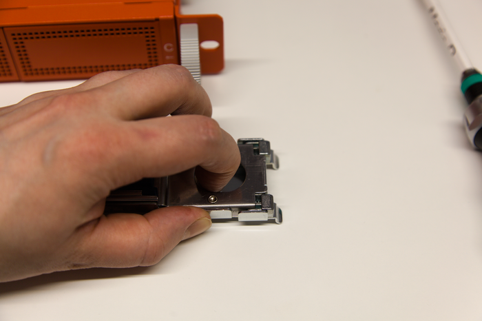
    • Release the lock with the help of the small lever
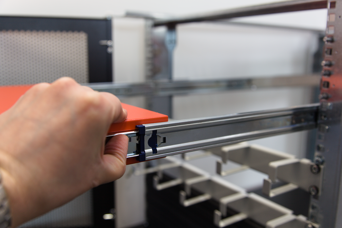
    • Remove the inner rail from the guide rail
    RC350 Rackmounting 05.png
    Fig. 5
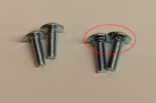
    Step 5
    • Inner rail with small fixing screws
    RC350 Rackmounting 06.png
    Fig. 6
    Step 6
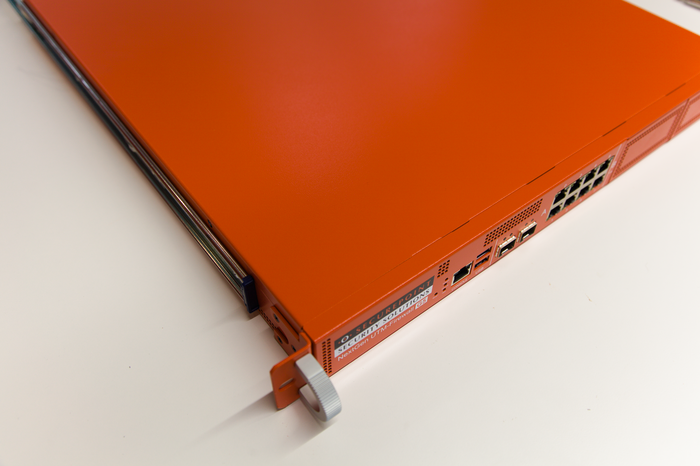
    • Mount the inner rail
    RC350 Rackmounting 07.png
    Fig. 7
    Step 7
    • Repeat steps #01 - #06 on the other side
    RC350 Rackmounting 08.png
    Fig. 8
    Step 8
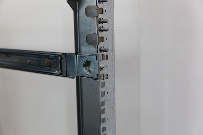
    • Pull back the bolt of the fastening device at the end of the guide rail to hook it in
    RC350 Rackmounting 09.png
    Fig. 9
    Step 9
    • Suspended premium guide rail
    RC350 Rackmounting 12.png
    Fig. 10
    Step 12
    • Screws for fixing the guide rails
  • Left: Screws for front
  • Right: screws for rear (with spacer)
  • RC350 Rackmounting 10.png
    Fig. 11
    Step 10
    • Attach guide rails to the back of the rack
  • Use screws with spacers
    • Tighten screws only hand-tight
    RC350 Rackmounting 11.png
    Fig. 12
    Step 11
    • Pull the inner rails forwards
    • To hook in the units, release the lock using the small lever
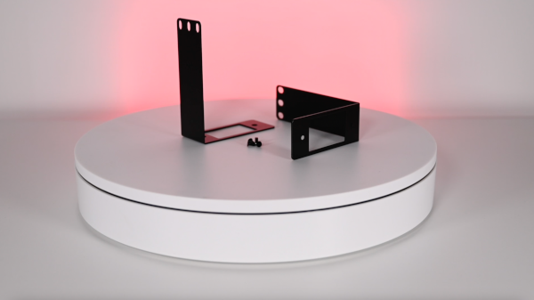
    RC350 Rackmounting 13.png
    Fig. 13
    Step 13
    • Fit the screws at the front
    • Tighten only slightly
    RC350 Rackmounting 14.png
    Fig. 14
    Step 14
  • Ready


  • Mounting RC350-RC1000R in rack