Creating and configuring a bond interface
New function with version: 12.6.1
notempty
This article refers to a Resellerpreview
Creating a bond interface
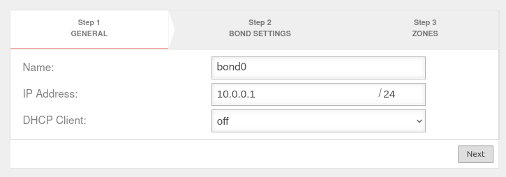
A bond interface is created under Area Network interfaces Button .
Edit bond interface
A bond interface is edited under Area Network interfaces Button .
General | ||||||||||
| Caption | Value | Description | UTMuser@firewall.name.fqdnNetworkNetwork configuration 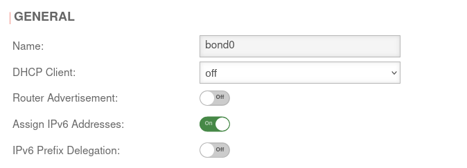 Tab General Tab General
| |||||||
|---|---|---|---|---|---|---|---|---|---|---|
| Name: | bond0 | |||||||||
| DHCP Client: | Here the setting is made whether - and if so, for which IP protocol - the interface should obtain its IP addresses from a DHCP server. | |||||||||
| Router Advertisement: | Off | If the UTM has received an IPv6 prefix (on an external interface), it can advertise the Default Gateway and the subnet via Router advertisement and at the same time distribute corresponding IPv6 addresses in the connected network. (See article IPv6 Prefix Delegation) | ||||||||
| Assign IPv6 addresses: | On | If it is not desired that the UTM distributes IPv6 addresses, but only the default gateway, then this option must be deactivated. | ||||||||
| IPv6 Prefix Delegation: | Off | Enables IPv6 prefix delegation to get IPv6 prefixes allocated on this interface. (For external interfaces only.) | ||||||||
Settings | ||||||||||
| MTU: | 1500 default | The Maximum Transmission Unit specifies the maximum packet size that can be transmitted without fragmentation. |  | |||||||
| Route Hint IPv4: | It is possible to define the gateway of the interface via the "Route Hint" field. This has the advantage, for example, that only the interface (e.g. LAN3) needs to be specified in routing and not the gateway IP directly. | |||||||||
| Route Hint IPv6: | It is possible to define the gateway of the interface via the "Route Hint" field. This has the advantage, for example, that only the interface (e.g. LAN3) needs to be specified in routing and not the gateway IP directly. | |||||||||
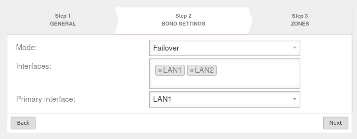
Bond settingsMode Failover Mode Failover
| ||||||||||
| Mode: | Failover | Only one interface is used and the others are only used as failover | 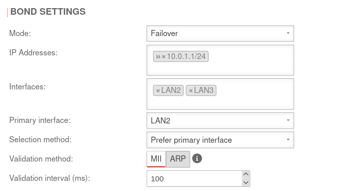 | |||||||
| IP addresses: | » ✕10.0.1.1/24 | IP address of the interface | ||||||||
| Interfaces: | » ✕LAN2 » ✕LAN3 | Selection of at least 2 interfaces | ||||||||
| Primary interface: | LAN2 | Assignment of the primary interface | ||||||||
| Selection method: | Prefer primary interface | The primary interface is activated whenever it is available. | ||||||||
| Only change in the event of errors | It is only changed if the active interface fails. If the primary interface fails, the system switches to the next interface If the primary interface is active again, the system does not switch back | |||||||||
| Prefer a better interface | The better interface is activated. If the primary interface fails, the system switches to the next interface If the primary interface is active again, the system uses the interface speed and duplex settings to determine the better interface and switches to it if necessary. | |||||||||
| Validation method: | MII only checks whether the interface is active (faster). | |||||||||
| ARP sends packets to the test endpoints (slower). | ||||||||||
| Validation interval (ms): | 100 | Zeitintervall in dem geprüft wird | ||||||||
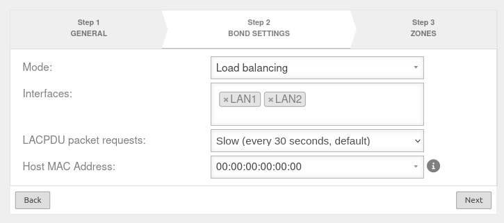
Mode Load balancing Mode Load balancing
| ||||||||||
| Mode: | Load balancing | The load is distributed across all interfaces |
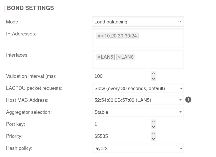 | |||||||
| IP addresses: | » ✕10.0.1.1/24 | IP address of the interface | ||||||||
| Validation interval (ms): | 100 | Zeitintervall in dem geprüft wird | ||||||||
| LACPDU packet requests: | Slow (every 30 seconds, default) | Link Aggregation Control Protocol Data Units provide information about the status of the interfaces | ||||||||
| fast (every second) | ||||||||||
| Host MAC address: | 00:00:00:00:00:00 | Defines the MAC address with which the bond interface exchanges LACPDU with the remote station. With the default setting (00:00:00:00:00:00:00), a MAC address is automatically selected for the interfaces involved, which is retained even if this interface fails. | ||||||||
| Aggregator selection: | If the interfaces involved are connected to different destinations, all connections to a destination are combined into an aggregator.
| |||||||||
| Stable | The active aggregator is selected based on the largest total bandwidth. | |||||||||
| Bandwidth: | The active aggregator is selected based on the largest total bandwidth. | |||||||||
| Number of ports: | The active aggregator is selected based on the most available interfaces (ports). | |||||||||
| Port key: | 1 | Defines duplex for the interface. Should only be adjusted if the LACP negotiation does not work and the remote station specifies a fixed one. In an AD system, the port key consists of three parts:<br
The values can be between 0 and 1023. | ||||||||
| Priority: | 65535 | The device with the lowest priority determines which physical interfaces from the bond are used. If the priority is the same on both sides, the responsible device is determined relatively randomly using other mechanisms. | ||||||||
| Hash method: | layer2 | Creates a hash with the data from layer 2 of the Ethernet packet. Packets with the same hash are sent via the same interface. | ||||||||
| layer2+3 | Creates a hash with the data from layer 2 and layer 3 of the Ethernet packet. Packets with the same hash are sent via the same interface. Layer 2+3 divides the data better. | |||||||||
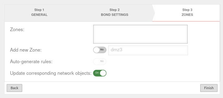
Zones | ||||||||||
| Zones: | Choose desired zones |  | ||||||||
| Update corresponding network objects: | On | If an existing zone has been selected, all network objects that are already in this zone and have an interface as a target are moved to the new interface. | ||||||||
DYNDNS | ||||||||||
| Enabled: | Yes | Enables or disables (default) the DynDNS function | 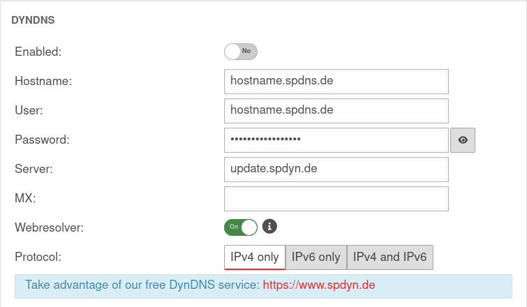 |
|||||||
| Hostname: | hostname.spdns.de | Desired Hostname | ||||||||
| User: | hostname.spdns.de | The corresponding user name must be entered here. | ||||||||
| Password: | The password must be entered here. | |||||||||
| Server: | update.spdyn.de | The securepoint update server | ||||||||
| MX: | ||||||||||
| Webresolver: | On | Must be activated if the NAT router is located before the DNS (i.e.: UTM → Fritzbox/Speedport → internet) | ||||||||
| Protocol: | The DNS service can be activated for IPv4 or IPv6 addresses only, or both IPv4 and IPv6. | |||||||||
Fallback | ||||||||||
| Fallback interface: | Interface that stands in for the main interface in the case of a malfunction. The absence of malfunctions is verified by ping-checking an IP. Further notes on the configuration of a fallback can be found in a separate Wiki article. |
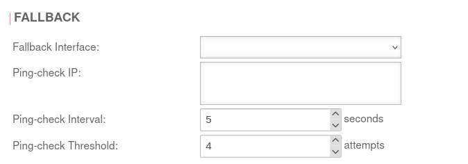 | ||||||||
| Ping-check IP: | Up to 4 hosts on which the ping check is to be carried out. This may also be a host in the internal network. If a ping check host does not respond, the next IP address is tried immediately. If none of the ping check hosts respond, this is considered a failed attempt and checked again after the ping check interval. | |||||||||
| Ping-check Interval: | 5 Seconds | Period between ping attempts | ||||||||
| Ping-check Threshold: | 4 Attempts | Number of failed ping attempts before switching to the fallback interface | ||||||||
