notempty
notempty
notempty Dieser Artikel bezieht sich auf eine nicht mehr aktuelle Version!
notempty
Der Artikel für die neueste Version steht hier
Zu diesem Artikel gibt es bereits eine neuere Version, die sich allerdings auf eine Beta-Version bezieht
Setting up a UTM with the installation wizard
Last adaptation to the version: 12.2.3
New:
- IPv6 Prefix Delegation configurable in Step 4
- The external interface is configured by default as DHCP client
- The protocol for the DHCP client on the external interface (A0) can be selected
This article refers to a Beta version
Prefaces
- Usually, the installation wizard appears during the initial setup of the UTM.
This checks whether a configuration already exists that is marked as the start configuration.
(Status )
If this is not the case, the wizard opens automatically.
- It is not advisable to start the installation wizard later, as other settings made in the meantime may be overwritten.
Installation wizard
Step 1 - General
| Caption | Value | Description | 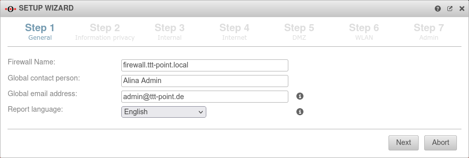 |
|---|---|---|---|
| Firewall Name: | firewall.ttt-point.local | This is about how the UTM responds to requests.
For example, if the mail relay is to be used, it may be useful to enter the Fully Qualified Domain Name (FQDN) of the mail exchange (MX) here so that other mail servers can match it via the reverse resolution of the PTR Resource Record (PTR). This setting is made in the Authentication → AD/LDAP Authentication → tab Settings Appliance Account entry. | |
| Global contact person: | Alina Admin | In this field, the name of the administrator or the organization is entered, which is later specified in the UTM error messages for questions. | |
| Global email address: | admin@ttt-point.de | Important system messages are sent to this email address. | |
| Language of reports: | Language in which the reports and system messages are sent | ||
Step 2 - Privacy | |||
| Anonymize all applications | Yes | When activated (default), the appliance's applications are anonymized in accordance with the GDPR. Under anonymization can also be activated individually for each application. |
 |
Step 3 - Internal | |||
| Internal firewall IP address: | 192.168.175.1/24 | The IP address of the internal interface (A1) as well as the subnet mask (as CIDR-notation) for the internal network. |  |
| Dynamically assign Client IP Addresses via DHCP: | No | When enabled Yes, the UTM works as a DHCP server: All clients in the internal network receive an IP address via DHCP. This sets the UTM as the default gateway and DNS server for the clients. | |
| Generate WLAN Bridge: Only if a WLAN module is present |
No | Creates a bridge so that this network and the WLAN are on the same network. | |
| Router advertisement: Only if no WLAN module is present |
No | If the UTM has received an IPv6 prefix, it can advertise the subnet via router advertisement in the network segment behind the interface. (See article IPv6 Prefix Delegation) | |
Step 4 - InternetThis is where the Internet connection is configured on the external interface (A0). | |||
Connection type DSL-PPPoE Connection type:
| |||
| With this type, an ADSL or SDSL modem is connected to the external interface (A0). The connection is initiated by the UTM. A router can be used under this connection type only if it can be set to a modem mode. | |||
| Username: | (Shares ISP) | The login information is provided by the ISP (Internet Service Provider) | 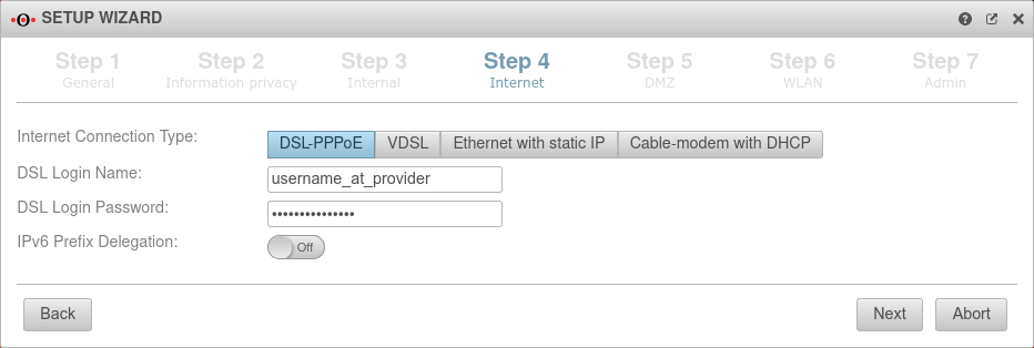 |
| Password: | (Shares ISP) | ||
| IPv6 Prefix Delegation: | Off | Allows an IPv6 network assigned by the Internet Service Provider to be split into /64 networks and assigned to individual interfaces via Router Advertisement. Example: Network assigned by ISP: 2001:0db8:aaaa:bb::/56 Networks distributed at internal interfaces via router adviertisement: 2001:0db8:aaaa:bb00::/64 2001:0db8:aaaa:bb01::/64 | |
Connection type VDSL Connection type:
| |||
| A VDSL modem is connected to the external interface (A0). The connection is initiated by the UTM. | |||
| Username: | (Shares ISP) | The login information is provided by the ISP (Internet Service Provider) | 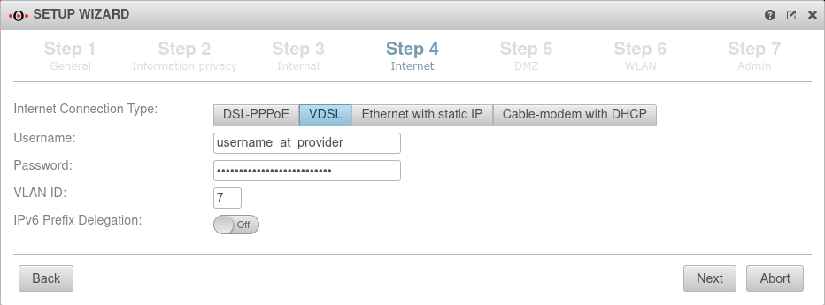 |
| Password: | (Shares ISP) | ||
| VLAN ID: | 7 | Will be supplied by the respective provider. The Deutsche Telekom usually uses, for example, the 7 as the VLAN ID. | |
| IPv6 Prefix Delegation: | Off | Allows an IPv6 network assigned by the Internet Service Provider to be split into /64 networks and assigned to individual interfaces via Router Advertisement. Example: Network assigned by ISP: 2001:0db8:aaaa:bb::/56 Networks distributed at internal interfaces via router adviertisement: 2001:0db8:aaaa:bb00::/64 2001:0db8:aaaa:bb01::/64 | |
Connection type Ethernet with static IP Connection type:
| |||
| With this connection type, a router is connected to the external interface (A0), which itself initiates the connection to the Internet. The login information of the provider is stored in the preceding router and not on the UTM. | |||
| External IP address: | 192.168.178.101/24 | The IP address of the external interface (A0) and the IP address range for the external network (subnet mask in CIDR notation). The default is an already existing IP address, if applicable. new as of 12.2.3: The external interface receives an IP address via DHCP by default, provided a DHCP server is available in the external network.
|
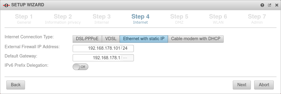 |
| Default gateway: | IP address of the default gateway for the UTM so that it knows which is the closest router for all networks that are not on an internal interface: As a rule: the Internet. | ||
| IPv6 Prefix Delegation: | Off | Allows an IPv6 network assigned by the Internet Service Provider to be split into /64 networks and assigned to individual interfaces via Router Advertisement. Example: Network assigned by ISP: 2001:0db8:aaaa:bb::/56 Networks distributed at internal interfaces via router adviertisement: 2001:0db8:aaaa:bb00::/64 2001:0db8:aaaa:bb01::/64 | |
Connection type Cable modem with DHCP Connection type:
Originally mostly devices that cable providers provided to their customers. | |||
| Also with this connection type, a router is connected to the external interface (A0), which itself initiates the connection to the Internet. The login information of the provider is stored in the preceding router and not on the UTM. |
 | ||
| DHCP client: | Selection with which protocol the interface receives IP addresses from the preceding router with DHCP server. | ||
| IPv6 Prefix Delegation: | Off | Allows an IPv6 network assigned by the Internet Service Provider to be split into /64 networks and assigned to individual interfaces via Router Advertisement. Example: Network assigned by ISP: 2001:0db8:aaaa:bb::/56 Networks distributed at internal interfaces via router adviertisement: 2001:0db8:aaaa:bb00::/64 2001:0db8:aaaa:bb01::/64 | |
Connection type LTE / others Connection type:
| |||
Step 5 - DMZConfiguration of a second internal network, often referred as Demilitarized Zone: Usually a network that is separate from the internal network. | |||
| DMZ IP address: | 192.168.176.1/24 | The IP address of the interface A2 and the subnet mask (as CIDR notation) for the DMZ network. |  |
| Assign the IP addresses to the clients in this network via DHCP: | No | When enabled Yes, the UTM works as a DHCP server: All clients in the DMZ network receive an IP address via DHCP. This sets the UTM as the default gateway and DNS server for the clients. | |
| Autogenerated rules: | No | Port filtering rules can be automatically created for this network, allowing traffic to the Internet on the interface to the external interface (A0). Likewise, rules are created that also allow traffic from the internal network into the DMZ network. These any rules are intended for testing purposes and should be disabled and replaced with well-defined rules in production mode. | |
| Generate WLAN Bridge: Only if a WLAN module is present |
No | Creates a bridge so that this network and the WLAN are on the same network. | |
| Router advertisement: | No | If the UTM has received an IPv6 prefix, it can advertise the subnet via router advertisement in the network segment behind the interface. (See article IPv6 Prefix Delegation) | |
Step 6 - WLANIn the delivery configuration, a WLAN module is installed in the UTM. | |||
| WLAN IP address: Not in bridge mode |
192.168.177.1/24 | The IP address of the WLAN interface (wlan0) and the subnet mask (as CIDR notation) for the WLAN network. In bridge mode, the setting from the internal network in which bridge mode was activated is used here. |
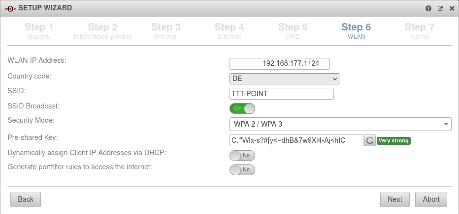 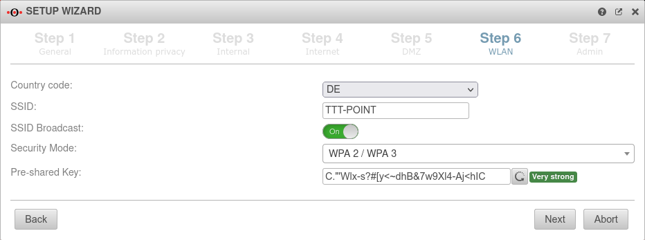 |
| Country code: | The country code is used to determine which frequencies and which signal strengths may be used. The frequencies used and the transmission power can be found in a Wikipedia article. | ||
| SSID: | TTT-POINT | The Service Set Identifier (SSID) is the name under which the WLAN network is presented to the clients. This must be entered in any case. | |
| SSID Broadcast: | On | This option can be used to define whether the WLAN network can be seen by every client or whether the transmission of the SSID should be suppressed. (Off) | |
| Security Mode | Is considered unsafe and only exists for backwards compatibility. (TKIP is used as encryption method) | ||
| Standard with enhanced security AES128 is used as encryption method: https://en.wikipedia.org/wiki/WPA2 | |||
| v12 | Standard with highest available level of security AES256 and SAE are used as encryption methodes: https://en.wikipedia.org/wiki/WPA3 | ||
| Assign the IP addresses to the clients in this network via DHCP: Not in bridge mode |
Off | When enabled Yes, the UTM works as a DHCP server: All clients in the WLAN network receive an IP address via DHCP. This sets the UTM as the default gateway and DNS server for the clients. In bridge mode, the setting from the internal network in which bridge mode was activated is used here. | |
| Pre-Shared key: | Don'tcopythis:Ei)#W~X$… | The base station and mobile device must have the same PSK (≙password). The security of the encryption depends directly on the length and complexity of the PSK! | |
| Automatically generates a very strong PSK | |||
| Generate rules for Internet access: Not in bridge mode |
Off | Port filtering rules can be automatically created for this network, allowing traffic to the Internet on the interface to the external interface (A0). Likewise, rules are created that also allow data traffic from the internal network into the WLAN network. These any rules are intended for testing purposes and should be disabled and replaced with well-defined rules in production mode. In bridge mode, the setting from the internal network in which bridge mode was activated is used here. | |
Step 7 - Administrator | |||
| User | admin | The username admin cannot be changed at this point |  |
| Password: | ••••••• | The admin password insecure is already insecure because it appears in all documentation for our UTM and must therefore be replaced as soon as possible with a very strong admin password. The new password must comply with the password guidelines.
Passwords must meet the following criteria:
| |
| Confirm password: | ••••••• | ||
| |||
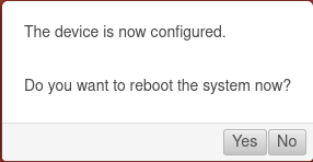
Reboot
| |||
| Do you want to reboot the system now? | In order for the configuration changes to be applied, the respective services must be restarted in the correct order.
|
 | |
| If your own IP address was changed to reach the admin interface of the UTM and the default was changed in Step 3 - Internal, the internal interface of the UTM is now located in this network.
For further configuration, the IP address of your own computer must then be changed again. See the [1] | |||


