notempty
- The firmware can be synchronized between master and spare
- Additional notes on Maintenance mode
The latest version of the software should always be installed.
Only the latest version contains the latest features, security enhancements and error corrections.
Fields of application
High availability of the UTM can be ensured by using the UTM in a hot standby cluster.
The UTMs within the cluster monitor each other and, if necessary, automatically switch to the device with the best status. Intervention by the administrator is not necessary.
Establishment
When setting up the UTM cluster, two UTMs with identical firmware are connected via a Hotwire interface. The installation with the "Cluster Setup Wizard" is performed on the Original UTM, which will be the MASTER in the newly created cluster. This UTM will be used to synchronize the configuration. On the Spare UTM, which will be the BACKUP in the cluster, the Hotwire interface is defined and an SSH key is generated during installation. The SSH key of the MASTER is also entered on the spare UTM.
The active UTM in the cluster, has the higher priority and is called the MASTER.
The UTM with the lower priority, the passive UTM, is the BACKUP.
Requirements
The following requirements are necessary for cluster operation:
- A cluster license
To configure and operate the UTM cluster, a valid cluster license is required, which can be applied for in the Securepoint Reseller Portal.
End customers are requested to contact their authorized Securepoint Reseller.
- Two identical appliances* with at least 3 Ethernet interfaces and the same firmware
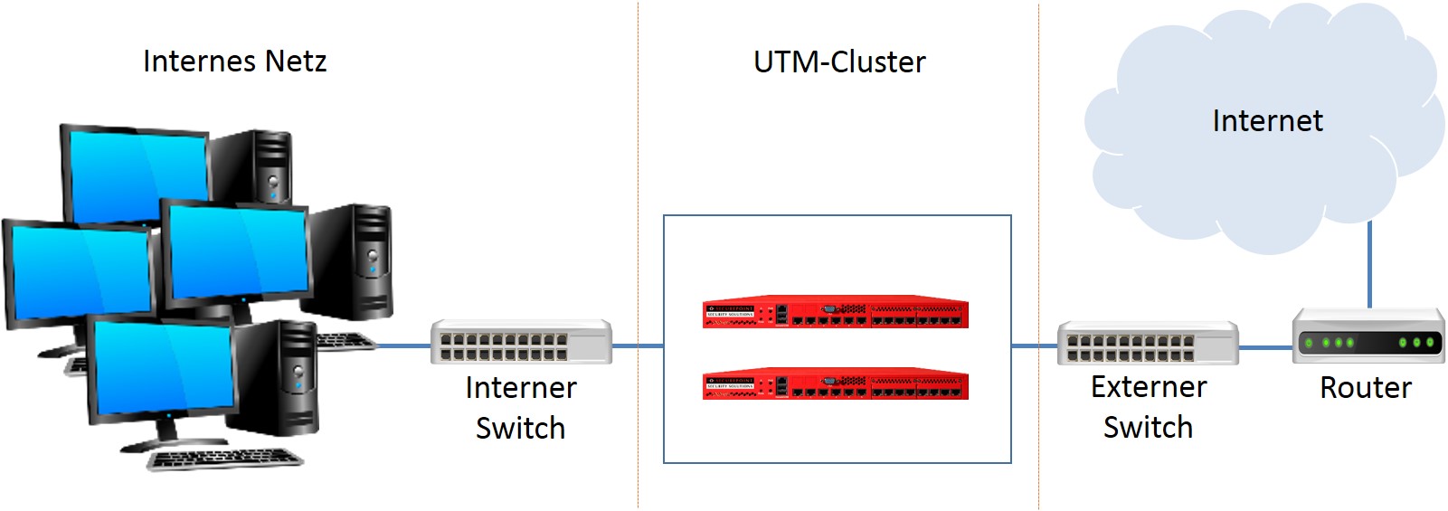
In the smallest scenario (see Figure 1.1) there is one input interface (internal LAN) and one output interface (external LAN) as well as the third free interface. This interface, also referred to as the Hotwire interface in the following, is required for configuration adjustment and connection tracking. It cannot take over any other network function.
- The used switches and routers support gratuitous ARP
If there is a master/backup change in the UTM cluster, the now active UTM sends gratuitous ARP packets to its environment to announce the new MAC address.
If the switches or routers do not support this function, they can only communicate via the active UTM with a delay.
Functionality of the cluster
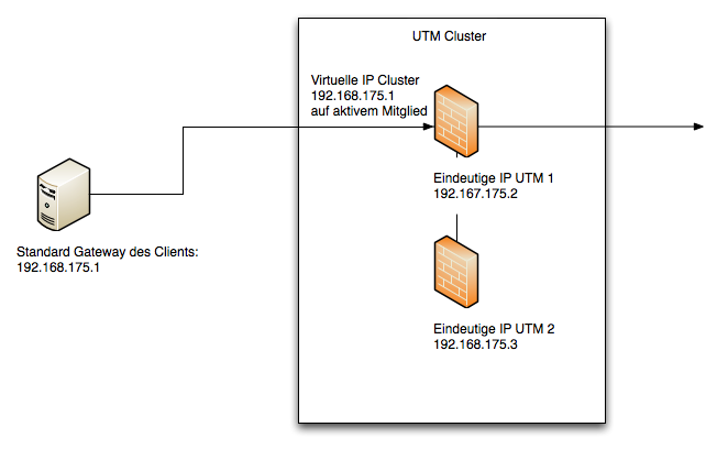
The cluster uses unique IP and MAC addresses for the two members of the cluster and virtual IP addresses for the cluster itself. The virtual IP addresses are only active on the active member of the UTM cluster. If the active member of the cluster fails completely or partially, the virtual IP addresses change to the second member of the cluster.
For the clients and servers in a cluster configuration, the virtual IP address is the communication partner in the routing (e.g. the standard gateway, see Fig. 1.2).
The Cluster VRR Protocol
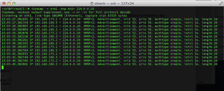
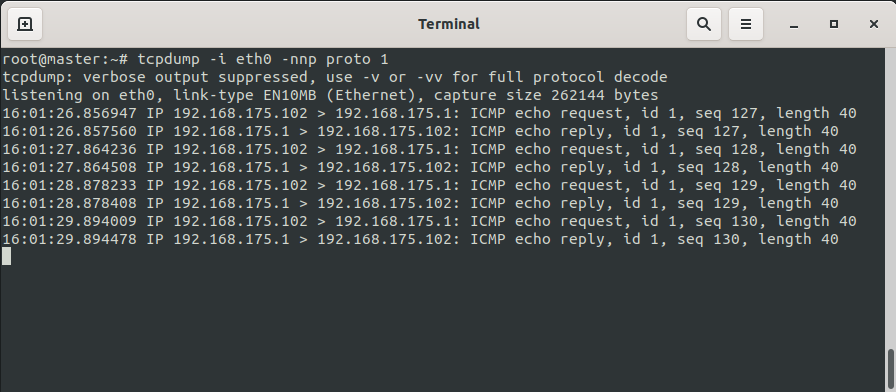
VRRP (Virtual Router Redundancy Protocol) is the communication protocol of the cluster. It is only active on interfaces that are configured as High-Availability interfaces. The master of the UTM cluster sends data packets to the backup via this protocol. If the backup does not receive any data packets, it upgrades itself to the master.
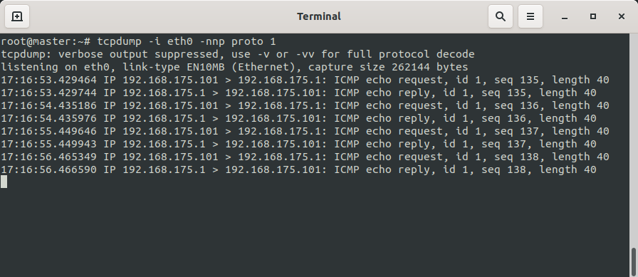
Using tcpdump the protocol can be made visible on a HA interface (see figure)
No special firewall rules are required to enable communication with the VRR protocol.
Switching the cluster
The following states or events trigger a switchover within the cluster:
- The active member of a cluster is restarted or shut down completely.
- One or more HA interfaces no longer have a physical link.
- The link of an HA interface is active, but due to a defective or incorrectly configured switch, the VRRP packets do not arrive at the cluster partner.
- The cluster function is deactivated on the active cluster partner by the administrator.
If more than two HA interfaces are activated, it is possible that a different number of HA interfaces may no longer be able to communicate in the event of an error. In this case, the UTM on which most interfaces have a link will become the active member as long as the UTMs still see each other via at least one HA interface. If the UTMs no longer see each other on any interface, both assume that the second member of the cluster no longer exists and both become the master.
Table, behavior in the cluster, example two HA interfaces:
| HA interface 1 | HA interface 2 | UTM 1 Status | UTM 2 Status |
|---|---|---|---|
| UTM 1 UPUTM 2 UP | UTM 1 UPUTM 2 UP | ||
| UTM 1 DOWNUTM 2 UP | UTM 1 UPUTM 2 UP | ||
| UTM 1 DOWNUTM 2 DOWN | UTM 1 UPUTM 2 UP | ||
| UTM 1 DOWNUTM 2 DOWN | UTM 1 UPUTM 2 DOWN | ||
| UTM 1 DOWNUTM 2 DOWN | UTM 1 DOWNUTM 2 DOWN |
Please note that UTM-1 has a higher priority than UTM-2. If the state in the table is active and marked as red, this means that the two members of the cluster no longer see each other and assume that the respective other partner is no longer present. Both members of the cluster are then active. However, network communication is then generally no longer possible because the problem is in the environment.
Fallback in a cluster
Here now the priority decides, because both machines are equally affected and the fallback of the Master becomes active.
Hotwire interface:
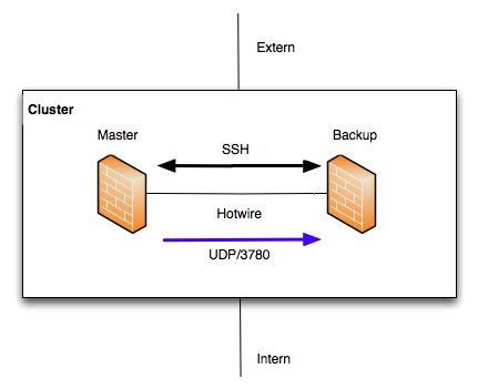
The Hotwire interface is an exclusive interface that is only used to synchronize the configuration of the cluster members and to synchronize the running connections (connection tracking). This interface has this task exclusively. When selecting the appliances, it must be ensured that one interface is free for the Hotwire network in each case.
The SSH protocol (TCP/22) is used to synchronize the configuration. The connection tracking is synchronized via port 3780 (UDP). If an Ethernet interface is marked as Hotwire, the rules for communication are generated automatically. For the SSH connection, public keys must be exchanged between the members of the UTM cluster. The configuration can be synchronized in both directions between the members of the cluster. The connection tracking is always automatically transferred from the master in the cluster to the backup (Fig. 1.3).
It must be ensured that nobody is administratively using the member of the cluster to which the synchronization is to be made at the time.
Adjusting the configuration
The respective start configuration is synchronized via the hotwire interface. Changes made on one machine in the cluster are transferred to the other device via this interface. Usually, after the cluster has been commissioned, the configuration is carried out on a UTM alone. We recommend using the master.
notempty
The following parts of the configuration are not adjusted:
- IP addresses that uniquely belong to a machine and are configured to Ethernet or VLAN interfaces.
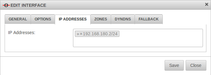
These are the IP addresses that are set in the web interface under the item. If an Ethernet or VLAN interface is newly created, this will be transmitted, but not the information about the IP addresses of these interfaces. If necessary, these must be configured manually on the cluster member, as they are always uniquely assigned to a UTM. These IP addresses are not to be confused with virtual IP addresses on an HA interface shared by both machines in the cluster. - Active Directory appliance account.
This account is always unique in AD. You create different names on both machines and log each one separately into Active Directory.
However, if the member of the UTM cluster is to be uniquely identified via this interface, this is necessary.
In this case, the virtual IP address is used to access the UTM that is the master at that moment.
Replacement unit configuration
(e.g. the master configuration must not be copied to the spare in order to change only the IP addresses).
If neither a local nor a cloud backup of the configuration is available, the replacement unit can be integrated into the cluster with a new configuration.
For this purpose, the setup steps as Spare must be carried out as described below: • Spare UTM with external modem • UTM_2 Spare UTM with external modem
Example configuration 1: External DSL modem
This example shows a configuration with which a UTM cluster can be operated on a DSL modem. The dial-up is done directly by the UTM.
Network configuration
LAN1: External DSL connection using PPPoE.
LAN2: Internal IP address: 192.168.12.141/24
LAN3: Hotwire IP address:192.168.180.2/24
Second member of the cluster (UTM 2, Spare)
LAN1: External DSL connection using PPPoE.
LAN2: Internal IP address:192.168.12.142/24
LAN3: Hotwire IP address:192.168.180.3/24
The virtual IP address is defined as 192.168.200.1/24.
This IP address is the default gateway of the internal network.
Otherwise the DHCP server would access the physical address of the spare UTM during the fallback and not synchronize the leases.
Preparations
Setting up the UTMs
- To set up the UTM cluster, the installation wizard is used first
- A (cluster) license is already required to log on to the UTM
- To prevent double dial-up, the DSL modem should not be connected
- Up to this point, the configuration of the two UTMs differs only in the internal and external IP address
- After the wizard is completed, the UTMs are restarted
IP addresses of the upcoming Hotwire interfaces
Connect Hotwire interface
The UTMs are now physically connected via the selected Hotwire interface. This must occupy the same port on the machines - Designation depending on the hardware and software used A2, eth2 or LAN3.
Cluster configuration
- The UTMs have different priorities within the cluster.
- The higher priority is given to the active device (Master), the lower to the backup system Spare.
- In our example, the UTM with the unique internal IP address 192.168.12.141 will be the master.
- Login via the web interface with this IP and the port for administration (Default: 11115).
Master-UTM
| Start the Cluster Setup Wizard at Master Tab Interfaces with Button | ||||||||||||||||||||||||||||||||||||||||||||||||||||||||||||||||||||||||||||||||||||||||||||||||||
Cluster Wizard Step 1 | ||||||||||||||||||||||||||||||||||||||||||||||||||||||||||||||||||||||||||||||||||||||||||||||||||
| Master-UTM | 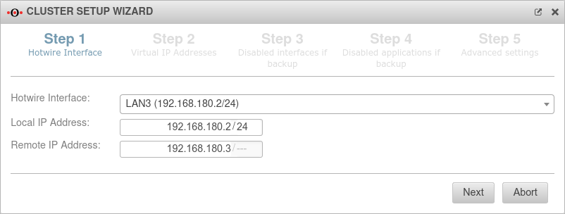 | |||||||||||||||||||||||||||||||||||||||||||||||||||||||||||||||||||||||||||||||||||||||||||||||||
|---|---|---|---|---|---|---|---|---|---|---|---|---|---|---|---|---|---|---|---|---|---|---|---|---|---|---|---|---|---|---|---|---|---|---|---|---|---|---|---|---|---|---|---|---|---|---|---|---|---|---|---|---|---|---|---|---|---|---|---|---|---|---|---|---|---|---|---|---|---|---|---|---|---|---|---|---|---|---|---|---|---|---|---|---|---|---|---|---|---|---|---|---|---|---|---|---|---|---|
| Hotwire interface:: | LAN3: 192.168.180.2/24 | |||||||||||||||||||||||||||||||||||||||||||||||||||||||||||||||||||||||||||||||||||||||||||||||||
| Local IP‑address: | 192.168.180.2/24 | IP address of the master UTM | ||||||||||||||||||||||||||||||||||||||||||||||||||||||||||||||||||||||||||||||||||||||||||||||||
| Remote IP‑address: | 192.168.180.3/--- | IP address of the Hotwire remote unit (spare UTM) | ||||||||||||||||||||||||||||||||||||||||||||||||||||||||||||||||||||||||||||||||||||||||||||||||
Cluster Wizard Step 2 | ||||||||||||||||||||||||||||||||||||||||||||||||||||||||||||||||||||||||||||||||||||||||||||||||||
| Interface: | The upcoming HA interface. In the example the internal interface. | 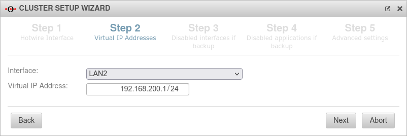 | ||||||||||||||||||||||||||||||||||||||||||||||||||||||||||||||||||||||||||||||||||||||||||||||||
| Virtual IP‑address: | 192.168.200.1/24 | The virtual IP address should be 192.168.200.1. There can also be several virtual IP addresses on one HA interface. | ||||||||||||||||||||||||||||||||||||||||||||||||||||||||||||||||||||||||||||||||||||||||||||||||
|
Otherwise the DHCP server would key itself to the physical address of the spare UTM during the fallback and not synchronize the leases. | ||||||||||||||||||||||||||||||||||||||||||||||||||||||||||||||||||||||||||||||||||||||||||||||||||
Cluster Wizard Step 3 | ||||||||||||||||||||||||||||||||||||||||||||||||||||||||||||||||||||||||||||||||||||||||||||||||||
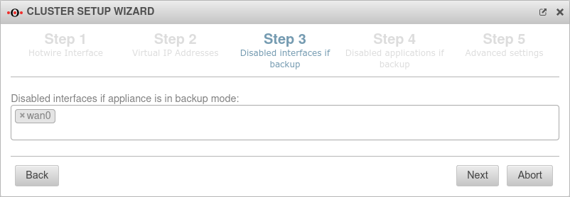
| Disabled interfaces while the device is in backup mode: ×wan0 |
Interfaces that are not booted on the backup system, the spare UTM. In the example wan0 (the DSL interface). The dial-in should only be done by the currently active master UTM in the cluster. This makes it possible to connect both external interfaces of the UTMs to the DSL modem. If the modem has only one LAN port, a separate switch must be used. |
 | ||||||||||||||||||||||||||||||||||||||||||||||||||||||||||||||||||||||||||||||||||||||||||||||||
Cluster Wizard Step 4 | ||||||||||||||||||||||||||||||||||||||||||||||||||||||||||||||||||||||||||||||||||||||||||||||||||
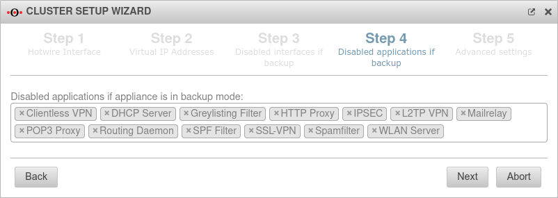
| Disabled applications while the device is in backup mode:×Clientless VPN ×DHCP Server ×Greylisting Filter ×HTTP Proxy ×IPSEC ×L2TP VPN ×Mailrelay ×POP3 Proxy ×Routing Daemon ×SPF Filter ×SSL-VPN ×Spamfilter ×WLAN ServerDefault | Here applications are listed that should be disabled by default if the spare UTM is in backup mode. It may not be possible to use Wireguard in cluster operation if the spare has a path towards the Wireguard peer, e.g. via a public management IP. In this case, the wireguard tunnel to the peer is established and there is a tunnel between the spare and the wireguard peer. The following command must then be entered (if the interface is wg0):
interface set name wg0 flags "DISABLED_IF_SPARE"
From UTM v12.4.0 this happens automatically, but for existing configurations this must be done retrospectively. |
 | ||||||||||||||||||||||||||||||||||||||||||||||||||||||||||||||||||||||||||||||||||||||||||||||||
Cluster Wizard Step 5 | ||||||||||||||||||||||||||||||||||||||||||||||||||||||||||||||||||||||||||||||||||||||||||||||||||
| Priority | High | The Master UTM receives the priority "high". | 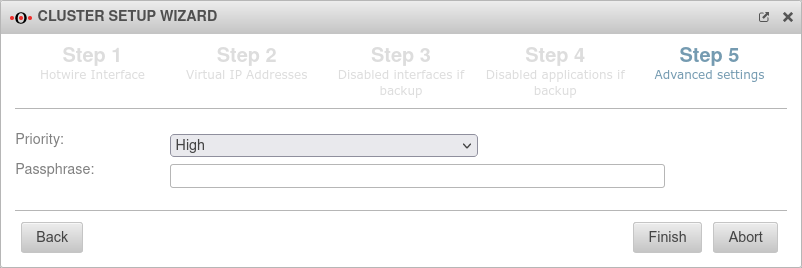 | |||||||||||||||||||||||||||||||||||||||||||||||||||||||||||||||||||||||||||||||||||||||||||||||
| Passphrase: | insecure | The passphrase for the communication between the two UTMs on the HA interfaces (VRR protocol) | ||||||||||||||||||||||||||||||||||||||||||||||||||||||||||||||||||||||||||||||||||||||||||||||||
| Close the Cluster Wizard with | ||||||||||||||||||||||||||||||||||||||||||||||||||||||||||||||||||||||||||||||||||||||||||||||||||
Status of the cluster configuration | ||||||||||||||||||||||||||||||||||||||||||||||||||||||||||||||||||||||||||||||||||||||||||||||||||
| Master Tab Interfaces | ||||||||||||||||||||||||||||||||||||||||||||||||||||||||||||||||||||||||||||||||||||||||||||||||||
| LAN2 | Interface used for High Availability | Virtual IP 192.168.200.1/24 IP address: 192.168.100.2/24 |
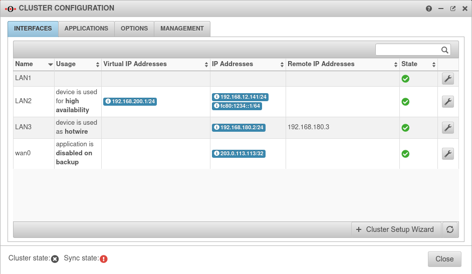 | |||||||||||||||||||||||||||||||||||||||||||||||||||||||||||||||||||||||||||||||||||||||||||||||
| LAN3 | Interface is used as Hotwire | IP address 192.168.180.2/24 | ||||||||||||||||||||||||||||||||||||||||||||||||||||||||||||||||||||||||||||||||||||||||||||||||
| wan0 | Interface is deactivated during backup | |||||||||||||||||||||||||||||||||||||||||||||||||||||||||||||||||||||||||||||||||||||||||||||||||
| Virtual IP addresses | 192.168.200.1/24 | This address is only available on the respective active Master device | ||||||||||||||||||||||||||||||||||||||||||||||||||||||||||||||||||||||||||||||||||||||||||||||||
| Remote IP addresses | 192.168.180.3 | Addresses of other devices in the cluster | ||||||||||||||||||||||||||||||||||||||||||||||||||||||||||||||||||||||||||||||||||||||||||||||||
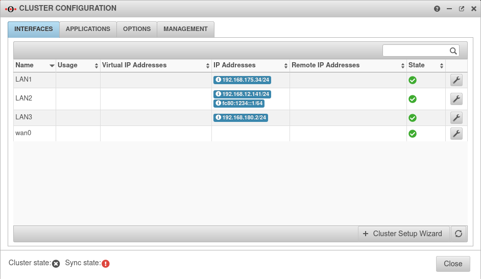
| Cluster state | offline | The cluster state does indicate offline (black) because the cluster is not yet set to active | ||||||||||||||||||||||||||||||||||||||||||||||||||||||||||||||||||||||||||||||||||||||||||||||||
| Sync state | error | The Sync state is shows error (red), because the remote terminal cannot be reached | ||||||||||||||||||||||||||||||||||||||||||||||||||||||||||||||||||||||||||||||||||||||||||||||||
Settings für cluster configuration | ||||||||||||||||||||||||||||||||||||||||||||||||||||||||||||||||||||||||||||||||||||||||||||||||||
| Master Tab Options | ||||||||||||||||||||||||||||||||||||||||||||||||||||||||||||||||||||||||||||||||||||||||||||||||||
| Cluster | Off | The cluster is not activated until both devices have the necessary SSH keys | 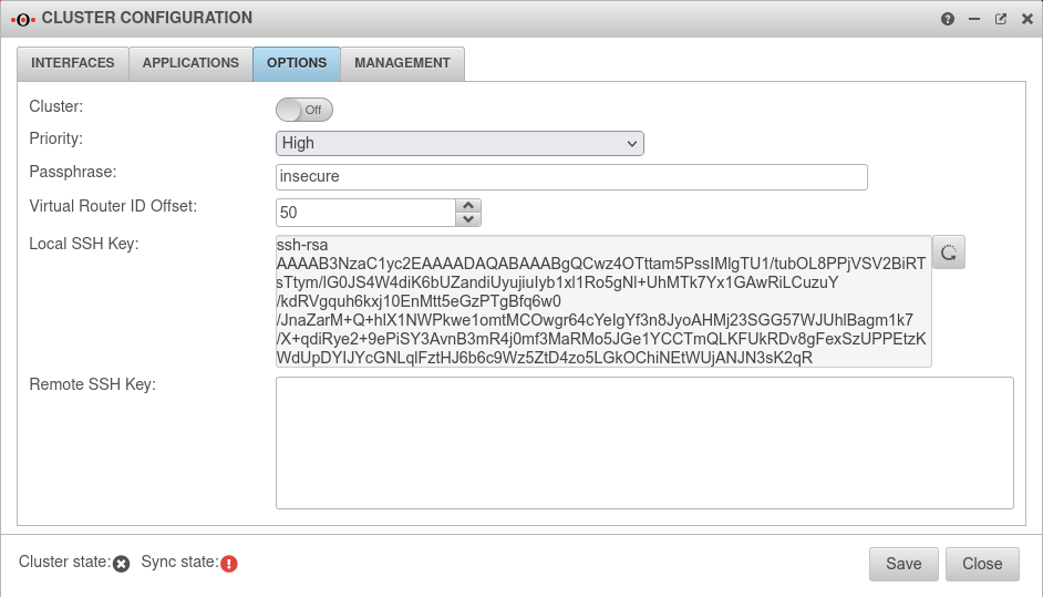 | |||||||||||||||||||||||||||||||||||||||||||||||||||||||||||||||||||||||||||||||||||||||||||||||
| Priority | The priority for the master remains at High | |||||||||||||||||||||||||||||||||||||||||||||||||||||||||||||||||||||||||||||||||||||||||||||||||
| Passphrase | The passphrase may be changed again here | |||||||||||||||||||||||||||||||||||||||||||||||||||||||||||||||||||||||||||||||||||||||||||||||||
| Virtual Router ID Offset: | 50 | Members of the same cluster must always have the same Virtual Router ID | ||||||||||||||||||||||||||||||||||||||||||||||||||||||||||||||||||||||||||||||||||||||||||||||||
| Local SSH Key: | Generate new local SSH key |
An SSH public key is created in the Options tab. | ||||||||||||||||||||||||||||||||||||||||||||||||||||||||||||||||||||||||||||||||||||||||||||||||
| ssh-rsa AAAAB3Nz […] zE0SU= root@master.cluster.local |
Copy SSH key to the clipboard | |||||||||||||||||||||||||||||||||||||||||||||||||||||||||||||||||||||||||||||||||||||||||||||||||
Spare-UTM | ||||||||||||||||||||||||||||||||||||||||||||||||||||||||||||||||||||||||||||||||||||||||||||||||||
| Spare UTM | ||||||||||||||||||||||||||||||||||||||||||||||||||||||||||||||||||||||||||||||||||||||||||||||||||
Spare interface configuration | ||||||||||||||||||||||||||||||||||||||||||||||||||||||||||||||||||||||||||||||||||||||||||||||||||
| Login to the web interface of the spare UTM Spare Tab Interfaces Button | ||||||||||||||||||||||||||||||||||||||||||||||||||||||||||||||||||||||||||||||||||||||||||||||||||
| Name: | LAN3 | LAN3 Edit interface | 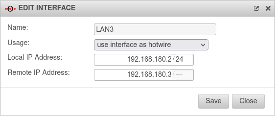 | |||||||||||||||||||||||||||||||||||||||||||||||||||||||||||||||||||||||||||||||||||||||||||||||
| Usage: | The interface eth2 of the spare UTM is marked as Hotwire. | |||||||||||||||||||||||||||||||||||||||||||||||||||||||||||||||||||||||||||||||||||||||||||||||||
| Local IP‑address: | 192.168.180.3/24 | IP address of the spare UTM to be used for Hotwire. | ||||||||||||||||||||||||||||||||||||||||||||||||||||||||||||||||||||||||||||||||||||||||||||||||
| Remote IP‑address: | 192.168.180.2 | IP address of the already configured Master UTM to be addressed as Hotwire. | ||||||||||||||||||||||||||||||||||||||||||||||||||||||||||||||||||||||||||||||||||||||||||||||||
Settings für cluster configuration | ||||||||||||||||||||||||||||||||||||||||||||||||||||||||||||||||||||||||||||||||||||||||||||||||||
| Spare Tab Options | ||||||||||||||||||||||||||||||||||||||||||||||||||||||||||||||||||||||||||||||||||||||||||||||||||
| Priority | The priority of the spare must be set to "Low". | 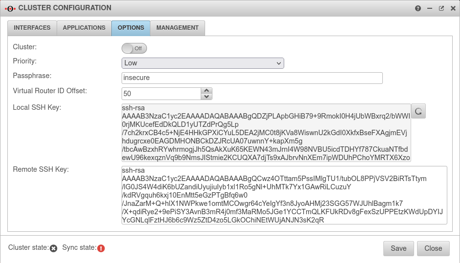 | ||||||||||||||||||||||||||||||||||||||||||||||||||||||||||||||||||||||||||||||||||||||||||||||||
| Passphrase: | insecure | The passphrase for the communication between the two UTMs on the HA interfaces (VRR protocol) | ||||||||||||||||||||||||||||||||||||||||||||||||||||||||||||||||||||||||||||||||||||||||||||||||
| Local SSH Key:① | Generate new local SSH key |
Create SSH Public Key for the Spare-UTM' | ||||||||||||||||||||||||||||||||||||||||||||||||||||||||||||||||||||||||||||||||||||||||||||||||
| ssh-rsa AAAAB3Nz […] Q1/k= root@spare.cluster.local |
Copy SSH key to the clipboard not yet | |||||||||||||||||||||||||||||||||||||||||||||||||||||||||||||||||||||||||||||||||||||||||||||||||
| SSH‑Key of the remote terminal: | ssh-rsa AAAAB3Nz […] zE0SU= root@master.cluster.local |
Paste public SSH key of the Master UTM from the clipboard | ||||||||||||||||||||||||||||||||||||||||||||||||||||||||||||||||||||||||||||||||||||||||||||||||
| Local SSH Key: ② | Now paste the local Public-SSH-Key of the spare UTM into the clipboard. | |||||||||||||||||||||||||||||||||||||||||||||||||||||||||||||||||||||||||||||||||||||||||||||||||
| Switch to Master Options | ||||||||||||||||||||||||||||||||||||||||||||||||||||||||||||||||||||||||||||||||||||||||||||||||||
| SSH‑Key of the remote terminal: | ssh-rsa AAAAB3Nz […] Q1/k= root@spare.cluster.local |
Paste public key of the spare UTM from the clipboard. On the Master-UTM the Spare-UTM represents the remote station | ||||||||||||||||||||||||||||||||||||||||||||||||||||||||||||||||||||||||||||||||||||||||||||||||
| On both sides there should now be a local SSH key and the SSH key of the remote terminal. Save the settings on both UTMs in this dialog by pressing the button. | ||||||||||||||||||||||||||||||||||||||||||||||||||||||||||||||||||||||||||||||||||||||||||||||||||
| Sync state | pending | The synchronization status should now change from error (red) to pending (yellow). This means that the two UTMs see each other via the Hotwire interface, but the configuration is not yet synchronized. The status is updated in certain intervals. In the tab interfaces the update can be triggered manually with the synchronize button . | ||||||||||||||||||||||||||||||||||||||||||||||||||||||||||||||||||||||||||||||||||||||||||||||||
Master Tab Management | ||||||||||||||||||||||||||||||||||||||||||||||||||||||||||||||||||||||||||||||||||||||||||||||||||
| Synchronize configuration | By clicking on the button, the configuration is transferred from the master to the spare. Another security query is displayed, which can be used to cancel the synchronization. |
 | ||||||||||||||||||||||||||||||||||||||||||||||||||||||||||||||||||||||||||||||||||||||||||||||||
| Sync state | synchronized | If the synchronization was completed successfully, the synchronization status is now green. The two UTMs are synchronized. This process can be checked by calling up a configuration on the spare UTM that has been changed in the Master. The cluster Priority Tab Settings of the spare UTM (backup) has been automatically set to low. | ||||||||||||||||||||||||||||||||||||||||||||||||||||||||||||||||||||||||||||||||||||||||||||||||
Activate cluster | ||||||||||||||||||||||||||||||||||||||||||||||||||||||||||||||||||||||||||||||||||||||||||||||||||
| Master & Spare Tab Options | ||||||||||||||||||||||||||||||||||||||||||||||||||||||||||||||||||||||||||||||||||||||||||||||||||
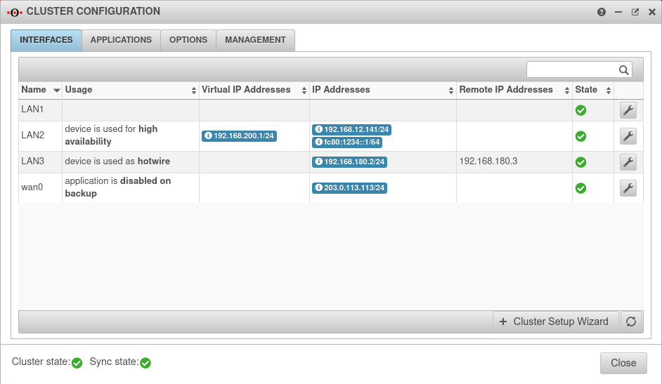 | ||||||||||||||||||||||||||||||||||||||||||||||||||||||||||||||||||||||||||||||||||||||||||||||||||
| Cluster: | On | This step must be executed at both UTMs. | ||||||||||||||||||||||||||||||||||||||||||||||||||||||||||||||||||||||||||||||||||||||||||||||||
| Cluster state | At the master UTM: | The cluster is now operational and the cluster master has the virtual IP address 192.168.200.1 on the internal interface. | ||||||||||||||||||||||||||||||||||||||||||||||||||||||||||||||||||||||||||||||||||||||||||||||||
| At the Spare UTM: | The Spare-UTM runs as hot standby in backup mode in the background | |||||||||||||||||||||||||||||||||||||||||||||||||||||||||||||||||||||||||||||||||||||||||||||||||
If the status is not updated immediately, this can again be triggered manually via the button for updating .
Example Configuration 2: External Router
- This example describes a configuration with an external router.
- The router is the gateway to the Internet.
- It is possible that a public network was given by the provider.
A private network is used in this example. The procedure is then the same as for the public network. - Two HA interfaces are now configured here.
One for the internal and one for the external interface.
Network configuration
First member of the cluster (UTM 1, Master)
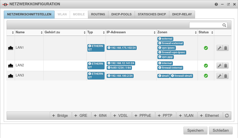
LAN1: External IP address (to router) 192.168.175.102/24
LAN2: Internal IP address: 192.168.12.141/24
LAN3: Hotwire IP address: 192.168.180.2/24
Second member of the cluster (UTM 2, Spare)
LAN1: External IP address (to the router) 192.168.175.103/24
LAN2: Internal IP address: 192.168.12.142/24
LAN3: Hotwire IP address: 192.168.180.3/24
The virtual IP addresses that both members of the cluster will share are:
External interfaces (to the router) 192.168.175.101/24.
Internal interfaces 192.168.200.1/24 | This IP is the default gateway of the internal network.
Preparations
Setting up the UTMs
- To set up the UTM cluster, the installation wizard is used first
- A (cluster) license is already required to log on to the UTM
- To prevent double dial-up, the DSL modem should not be connected
- Up to this point, the configuration of the two UTMs differs only in the internal and external IP address
- After the wizard is completed, the UTMs are restarted
IP addresses of the upcoming Hotwire interfaces
Connect Hotwire interface
The UTMs are now physically connected via the selected Hotwire interface. This must occupy the same port on the machines - Designation depending on the hardware and software used A2, eth2 or LAN3.
Cluster configuration
- The UTMs have different priorities within the cluster.
- The higher priority is given to the active device (Master), the lower to the backup system Spare.
- In our example, the UTM with the unique internal IP address 192.168.12.141 will be the master.
- Login via the web interface with this IP and the port for administration (Default: 11115).
Master-UTM
| Start the Cluster Setup Wizard at Master Tab Interfaces with Button | ||||||||||||||||||||||||||||||||||||||||||||||||||||||||||||||||||||||||||||||||||||||||||||||||||
Cluster Wizard Step 1 | ||||||||||||||||||||||||||||||||||||||||||||||||||||||||||||||||||||||||||||||||||||||||||||||||||
| Master-UTM |  | |||||||||||||||||||||||||||||||||||||||||||||||||||||||||||||||||||||||||||||||||||||||||||||||||
|---|---|---|---|---|---|---|---|---|---|---|---|---|---|---|---|---|---|---|---|---|---|---|---|---|---|---|---|---|---|---|---|---|---|---|---|---|---|---|---|---|---|---|---|---|---|---|---|---|---|---|---|---|---|---|---|---|---|---|---|---|---|---|---|---|---|---|---|---|---|---|---|---|---|---|---|---|---|---|---|---|---|---|---|---|---|---|---|---|---|---|---|---|---|---|---|---|---|---|
| Hotwire interface:: | LAN3: 192.168.180.2/24 | |||||||||||||||||||||||||||||||||||||||||||||||||||||||||||||||||||||||||||||||||||||||||||||||||
| Local IP‑address: | 192.168.180.2/24 | IP address of the master UTM | ||||||||||||||||||||||||||||||||||||||||||||||||||||||||||||||||||||||||||||||||||||||||||||||||
| Remote IP‑address: | 192.168.180.3/--- | IP address of the Hotwire remote unit (spare UTM) | ||||||||||||||||||||||||||||||||||||||||||||||||||||||||||||||||||||||||||||||||||||||||||||||||
Cluster Wizard Step 2 | ||||||||||||||||||||||||||||||||||||||||||||||||||||||||||||||||||||||||||||||||||||||||||||||||||
| Interface: | The upcoming HA interface. In the example the internal interface. |  | ||||||||||||||||||||||||||||||||||||||||||||||||||||||||||||||||||||||||||||||||||||||||||||||||
| Virtual IP‑address: | 192.168.200.1/24 | The virtual IP address should be 192.168.200.1. There can also be several virtual IP addresses on one HA interface. | ||||||||||||||||||||||||||||||||||||||||||||||||||||||||||||||||||||||||||||||||||||||||||||||||
|
Otherwise the DHCP server would key itself to the physical address of the spare UTM during the fallback and not synchronize the leases. | ||||||||||||||||||||||||||||||||||||||||||||||||||||||||||||||||||||||||||||||||||||||||||||||||||
Cluster Wizard Step 3 | ||||||||||||||||||||||||||||||||||||||||||||||||||||||||||||||||||||||||||||||||||||||||||||||||||
| Disabled interfaces while the device is in backup mode: |
Interfaces that are not booted on the backup system, the spare UTM. In this configuration, that is not required | 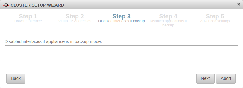 | ||||||||||||||||||||||||||||||||||||||||||||||||||||||||||||||||||||||||||||||||||||||||||||||||
Cluster Wizard Step 4 | ||||||||||||||||||||||||||||||||||||||||||||||||||||||||||||||||||||||||||||||||||||||||||||||||||
| Disabled applications while the device is in backup mode: ×Clientless VPN ×DHCP Server ×Greylisting Filter ×HTTP Proxy ×IPSEC ×L2TP VPN ×Mailrelay ×POP3 Proxy ×Routing Daemon ×SPF Filter ×SSL-VPN ×Spamfilter ×WLAN ServerDefault | Here applications are listed that should be disabled by default if the spare UTM is in backup mode. |  | ||||||||||||||||||||||||||||||||||||||||||||||||||||||||||||||||||||||||||||||||||||||||||||||||
Cluster Wizard Step 5 | ||||||||||||||||||||||||||||||||||||||||||||||||||||||||||||||||||||||||||||||||||||||||||||||||||
| Priority | High | The Master UTM receives the priority "high". |  | |||||||||||||||||||||||||||||||||||||||||||||||||||||||||||||||||||||||||||||||||||||||||||||||
| Passphrase: | insecure | The passphrase for the communication between the two UTMs on the HA interfaces (VRR protocol) | ||||||||||||||||||||||||||||||||||||||||||||||||||||||||||||||||||||||||||||||||||||||||||||||||
| Close the Cluster Wizard with | ||||||||||||||||||||||||||||||||||||||||||||||||||||||||||||||||||||||||||||||||||||||||||||||||||
Status of the cluster configuration | ||||||||||||||||||||||||||||||||||||||||||||||||||||||||||||||||||||||||||||||||||||||||||||||||||
| Master Tab Interfaces | ||||||||||||||||||||||||||||||||||||||||||||||||||||||||||||||||||||||||||||||||||||||||||||||||||
| LAN1 | (Interface is not yet configured for HA) | IP address 192.168.175.102/24 | 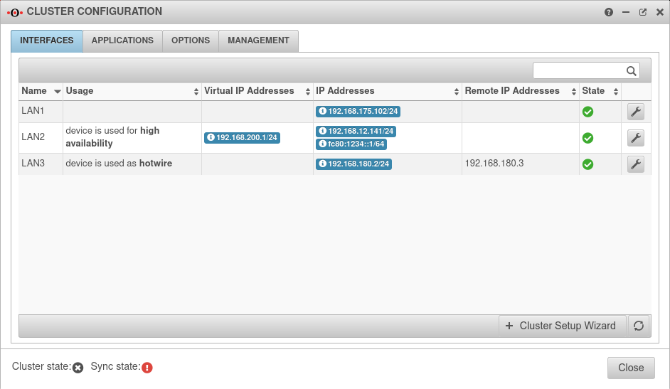 | |||||||||||||||||||||||||||||||||||||||||||||||||||||||||||||||||||||||||||||||||||||||||||||||
| LAN2 | Interface used for High Availability | Virtual IP 192.168.200.1/24 IP address: 192.168.100.2/24 | ||||||||||||||||||||||||||||||||||||||||||||||||||||||||||||||||||||||||||||||||||||||||||||||||
| LAN3 | Interface is used as Hotwire | IP address 192.168.180.2/24 | ||||||||||||||||||||||||||||||||||||||||||||||||||||||||||||||||||||||||||||||||||||||||||||||||
| Virtual IP addresses | 192.168.200.1/24 | This address is only available on the respective active Master device | ||||||||||||||||||||||||||||||||||||||||||||||||||||||||||||||||||||||||||||||||||||||||||||||||
| Remote IP addresses | 192.168.180.3 | Addresses of other devices in the cluster | ||||||||||||||||||||||||||||||||||||||||||||||||||||||||||||||||||||||||||||||||||||||||||||||||
| Cluster state | offline | The cluster state does indicate offline (black) because the cluster is not yet set to active | ||||||||||||||||||||||||||||||||||||||||||||||||||||||||||||||||||||||||||||||||||||||||||||||||
| Sync state | error | The Sync state is shows error (red), because the remote terminal cannot be reached | ||||||||||||||||||||||||||||||||||||||||||||||||||||||||||||||||||||||||||||||||||||||||||||||||
Settings für cluster configuration | ||||||||||||||||||||||||||||||||||||||||||||||||||||||||||||||||||||||||||||||||||||||||||||||||||
| Master Tab Options | ||||||||||||||||||||||||||||||||||||||||||||||||||||||||||||||||||||||||||||||||||||||||||||||||||
| Cluster | Off | The cluster is not activated until both devices have the necessary SSH keys |  | |||||||||||||||||||||||||||||||||||||||||||||||||||||||||||||||||||||||||||||||||||||||||||||||
| Priority | The priority for the master remains at High | |||||||||||||||||||||||||||||||||||||||||||||||||||||||||||||||||||||||||||||||||||||||||||||||||
| Passphrase | The passphrase may be changed again here | |||||||||||||||||||||||||||||||||||||||||||||||||||||||||||||||||||||||||||||||||||||||||||||||||
| Virtual Router ID Offset: | 50 | Members of the same cluster must always have the same Virtual Router ID | ||||||||||||||||||||||||||||||||||||||||||||||||||||||||||||||||||||||||||||||||||||||||||||||||
| Local SSH Key: | Generate new local SSH key |
An SSH public key is created in the Options tab. | ||||||||||||||||||||||||||||||||||||||||||||||||||||||||||||||||||||||||||||||||||||||||||||||||
| ssh-rsa AAAAB3Nz […] zE0SU= root@master.cluster.local |
Copy SSH key to the clipboard | |||||||||||||||||||||||||||||||||||||||||||||||||||||||||||||||||||||||||||||||||||||||||||||||||
Spare-UTM | ||||||||||||||||||||||||||||||||||||||||||||||||||||||||||||||||||||||||||||||||||||||||||||||||||
| Spare UTM | ||||||||||||||||||||||||||||||||||||||||||||||||||||||||||||||||||||||||||||||||||||||||||||||||||
Spare interface configuration | ||||||||||||||||||||||||||||||||||||||||||||||||||||||||||||||||||||||||||||||||||||||||||||||||||
| Login to the web interface of the spare UTM Spare Tab Interfaces Button | ||||||||||||||||||||||||||||||||||||||||||||||||||||||||||||||||||||||||||||||||||||||||||||||||||
| Name: | LAN3 | LAN3 Edit interface |  | |||||||||||||||||||||||||||||||||||||||||||||||||||||||||||||||||||||||||||||||||||||||||||||||
| Usage: | The interface eth2 of the spare UTM is marked as Hotwire. | |||||||||||||||||||||||||||||||||||||||||||||||||||||||||||||||||||||||||||||||||||||||||||||||||
| Local IP‑address: | 192.168.180.3/24 | IP address of the spare UTM to be used for Hotwire. | ||||||||||||||||||||||||||||||||||||||||||||||||||||||||||||||||||||||||||||||||||||||||||||||||
| Remote IP‑address: | 192.168.180.2 | IP address of the already configured Master UTM to be addressed as Hotwire. | ||||||||||||||||||||||||||||||||||||||||||||||||||||||||||||||||||||||||||||||||||||||||||||||||
Settings für cluster configuration | ||||||||||||||||||||||||||||||||||||||||||||||||||||||||||||||||||||||||||||||||||||||||||||||||||
| Spare Tab Options | ||||||||||||||||||||||||||||||||||||||||||||||||||||||||||||||||||||||||||||||||||||||||||||||||||
| Priority | The priority of the spare must be set to "Low". |  | ||||||||||||||||||||||||||||||||||||||||||||||||||||||||||||||||||||||||||||||||||||||||||||||||
| Passphrase: | insecure | The passphrase for the communication between the two UTMs on the HA interfaces (VRR protocol) | ||||||||||||||||||||||||||||||||||||||||||||||||||||||||||||||||||||||||||||||||||||||||||||||||
| Local SSH Key:① | Generate new local SSH key |
Create SSH Public Key for the Spare-UTM' | ||||||||||||||||||||||||||||||||||||||||||||||||||||||||||||||||||||||||||||||||||||||||||||||||
| ssh-rsa AAAAB3Nz […] Q1/k= root@spare.cluster.local |
Copy SSH key to the clipboard not yet | |||||||||||||||||||||||||||||||||||||||||||||||||||||||||||||||||||||||||||||||||||||||||||||||||
| SSH‑Key of the remote terminal: | ssh-rsa AAAAB3Nz […] zE0SU= root@master.cluster.local |
Paste public SSH key of the Master UTM from the clipboard | ||||||||||||||||||||||||||||||||||||||||||||||||||||||||||||||||||||||||||||||||||||||||||||||||
| Local SSH Key: ② | Now paste the local Public-SSH-Key of the spare UTM into the clipboard. | |||||||||||||||||||||||||||||||||||||||||||||||||||||||||||||||||||||||||||||||||||||||||||||||||
| Switch to Master {{Menu|Network|Cluster configuration | ||||||||||||||||||||||||||||||||||||||||||||||||||||||||||||||||||||||||||||||||||||||||||||||||||
| SSH‑Key of the remote terminal: | ssh-rsa AAAAB3Nz […] Q1/k= root@spare.cluster.local |
Paste public key of the spare UTM from the clipboard. On the Master-UTM the Spare-UTM represents the remote station | ||||||||||||||||||||||||||||||||||||||||||||||||||||||||||||||||||||||||||||||||||||||||||||||||
| On both sides there should now be a local SSH key and the SSH key of the remote terminal. Save the settings on both UTMs in this dialog by pressing the button. | ||||||||||||||||||||||||||||||||||||||||||||||||||||||||||||||||||||||||||||||||||||||||||||||||||
| Sync state | pending | The synchronization status should now change from error (red) to pending (yellow). This means that the two UTMs see each other via the Hotwire interface, but the configuration is not yet synchronized. The status is updated in certain intervals. In the tab interfaces the update can be triggered manually with the synchronize button . | ||||||||||||||||||||||||||||||||||||||||||||||||||||||||||||||||||||||||||||||||||||||||||||||||
Configure external interface to HA operation | ||||||||||||||||||||||||||||||||||||||||||||||||||||||||||||||||||||||||||||||||||||||||||||||||||
| Master & Spare LAN1 | ||||||||||||||||||||||||||||||||||||||||||||||||||||||||||||||||||||||||||||||||||||||||||||||||||
| Name: | LAN1 | Configure external interface to HA operation | 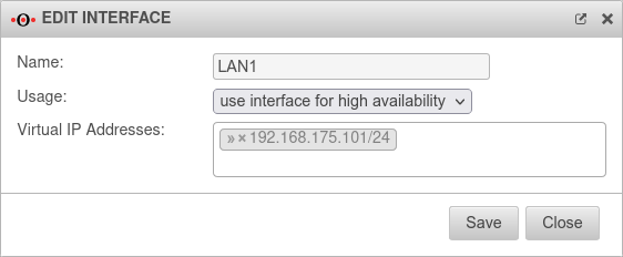 | |||||||||||||||||||||||||||||||||||||||||||||||||||||||||||||||||||||||||||||||||||||||||||||||
| Usage: | Configure high availability | |||||||||||||||||||||||||||||||||||||||||||||||||||||||||||||||||||||||||||||||||||||||||||||||||
| Virtuelle IP-Adressen: | » ✕192.168.175.101/24 | Virtual IP address from the network of the router | ||||||||||||||||||||||||||||||||||||||||||||||||||||||||||||||||||||||||||||||||||||||||||||||||
Master Tab Management | ||||||||||||||||||||||||||||||||||||||||||||||||||||||||||||||||||||||||||||||||||||||||||||||||||
| Synchronize configuration | By clicking on the button, the configuration is transferred from the master to the spare. Another security query is displayed, which can be used to cancel the synchronization. |
 | ||||||||||||||||||||||||||||||||||||||||||||||||||||||||||||||||||||||||||||||||||||||||||||||||
| Sync state | synchronized | If the synchronization was completed successfully, the synchronization status is now green. The two UTMs are synchronized. This process can be checked by calling up a configuration on the spare UTM that has been changed in the Master. The cluster Priority Tab Settings of the spare UTM (backup) has been automatically set to low. | ||||||||||||||||||||||||||||||||||||||||||||||||||||||||||||||||||||||||||||||||||||||||||||||||
Activate cluster | ||||||||||||||||||||||||||||||||||||||||||||||||||||||||||||||||||||||||||||||||||||||||||||||||||
| Master & Spare Tab Options | ||||||||||||||||||||||||||||||||||||||||||||||||||||||||||||||||||||||||||||||||||||||||||||||||||
| Cluster | On → | This step must be executed at both UTMs. | 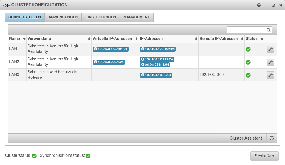 | |||||||||||||||||||||||||||||||||||||||||||||||||||||||||||||||||||||||||||||||||||||||||||||||
| Cluster state | At the master UTM: | The cluster is now operational and the cluster master has the virtual IP address 192.168.200.1 on the internal interface. | ||||||||||||||||||||||||||||||||||||||||||||||||||||||||||||||||||||||||||||||||||||||||||||||||
| At the Spare UTM: | The Spare-UTM runs as hot standby in backup mode in the background | |||||||||||||||||||||||||||||||||||||||||||||||||||||||||||||||||||||||||||||||||||||||||||||||||
NAT in the cluster configuration
We refer here to the example »Cluster configuration: External router«.
The external virtual IP address of the cluster is in the same broadcast domain as the external IP addresses of the interfaces.
The default route of the UTMs points to the router that connects to the Internet.
| External IP UTM 1 Master | 192.168.175.102/24 |
| External IP UTM 2 Spare | 192.168.175.103/24 |
| Virtual IP Cluster Cluster | 192.168.175.101/24 |
| IP of the Router | 192.168.175.1/24 |
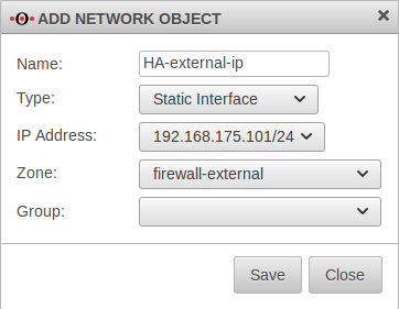
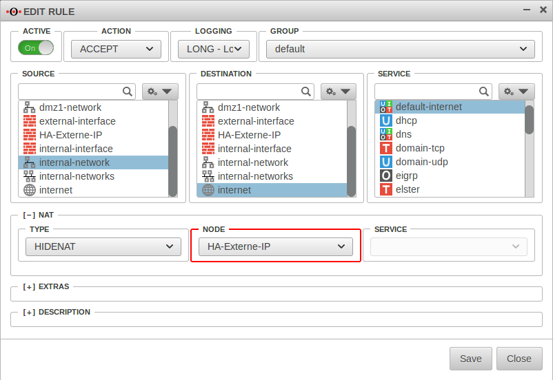
To change this, create a new object with the virtual IP address on the cluster interface in the menu Master on the tab Network Objects.
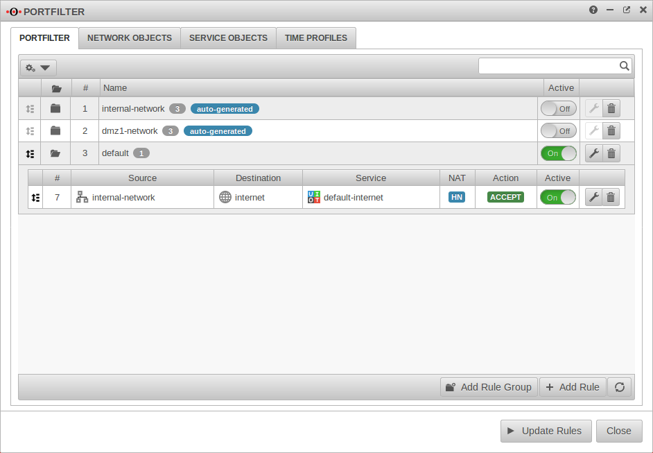
Master Button
If the ping test is now repeated, the cluster IP 192.168.175.101 is used.
The ping must be interrupted. After 30 seconds at the earliest the ping can be restarted.
notempty
This applies not only to HideNATs but also to port forwarding or destination NATs.
Applications in the cluster configuration
Applications use IP addresses to identify themselves to other servers.
For some applications, it is possible to set the cluster IP for this.
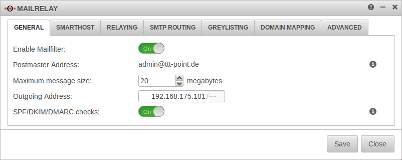
This is shown here as an example for the mailrelay.
Emails are to be sent and received via the mailrelay of the UTMs.
For this purpose, corresponding PTR, A, MX records and SPF entries were made in the TXT records of the domain, which point to the external virtual IP address of the cluster.
In order for the mail relay to send emails via this virtual IP, the outgoing IP address must be set correctly in the application. In our case the virtual IP 192.168.175.101
Then the cluster configuration must be synchronized again.
Communication of applications running on the firewall
All applications that establish a connection from the firewall itself use the primary IPs of the interfaces for this purpose (unless otherwise configured). If management IPs from the same broadcast domain are used, these primary IPs are not the virtual IP addresses.
Syslog
Syslog messages are sent by the management IP of the master if it is the active machine in the cluster, and by the management IP of the spare if it has been activated.
Http-proxy
If a parent proxy is in use, which accepts connections only from a certain IP, it must be configured in the menu Tab General → Outgoing address can be specified.
Mailrelay
If a parent proxy is in use, which accepts connections only from a certain IP, it must be configured in the menu Tab General → Outgoing address can be specified.
RADIUS/LDAP/AD connection
If the server only allows connections from certain IPs, the management IPs of both devices must be released on the target server.
IPSec
All IPSec connections must be adjusted in phase 1 so that one of the virtual IPs is permanently entered in the "Local Gateway" field.
→ → General Local Gateway
SSL-VPN Server
In all SSL-VPN server instances the option Multihome must be activated:
Button Tab Advanced
Communication with applications running on other devices
SSL-VPN Clients
All SSL-VPN client instances must be customized to use one of the virtual IPs to connect. The following CLI commands are required for this:
| Meaning | |
|---|---|
| master.cluster.local> openvpn get | Determines the ID of the SSL-VPN connection |
| master.cluster.local> openvpn set id <ID> local_addr <VIRTUELLE-IP> local_port <FREIER-PORT> | Sets the local address |
| master.cluster.local> appmgmt restart application openvpn | Enables the settings |
| Example | |
| master.cluster.local> openvpn get [...] master.cluster.local> openvpn set id <1> local_addr <192.168.175.101> local_port <20000> master.cluster.local> appmgmt restart application openvpn |
Example |
POP3 Proxy
The POP3 proxy always communicates 'with the management IP, if this is in the same broadcast domain as the default gateway. This should be noted when restricting access to POP3 servers to certain IP addresses in their configuration.
Clientless VPN
Connections to RDP/VNC servers are always established with the management IPs. This must be considered when restricting access to RDP/VNC servers to certain IP addresses in their configuration.
Nameserver
Connections to DNS servers are always established with the management IPs. This must be taken into account when restricting access to DNS servers to certain IP addresses in their configuration.
Restrictions
Combine DHCP client with HA interface
If the DHCP server is not available after you have started the UTM and it is also the master in the cluster at that moment, the virtual IP address is removed from the interface as soon as the DHCP server is available again and the UTM receives a new IP address from the DHCP server.
DHCP server in a cluster environment
Otherwise the DHCP server would key itself to the physical address of the spare UTM during the fallback and would not synchronize the leases. See: Cluster Configuration Step 2
