

Instructions for installing a Securepoint UTM G5 in a server rack.
Last adaption: 01.2025
New:
- Installation instructions for Black Dwarf G5
- Installation instructions for the new>/u> (2024)Premium Kit for the RC100
notempty
This article refers to a Beta version
Specification
notempty
Hint
- For reliable operation of our hardware throughout its life cycle, it must be operated within its specifications:
- The maximum ambient temperature for operation is 40°C
- The minimum ambient temperature for operation is 0°C
- Relative humidity must be between 10% and 80% and condensation must be prevent
- The maximum ambient temperature for operation is 40°C
- For installation, make sure that the firewall is mounted/set up as follows:
- Sufficient supply of cool air
- The device must not be covered
- The device must be as free-standing as possible
- When mounting in a network rack, special attention must be paid to:
- The rack must be ventilated
- Passively cooled devices (Black Dwarf G3+G5, RC100 G3, RC200 G3) must not be placed directly below or above heat emitting devices.
- There must be no build-up of heat
Black Dwarf G5
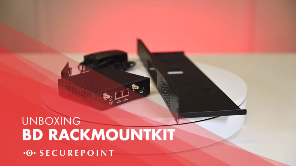
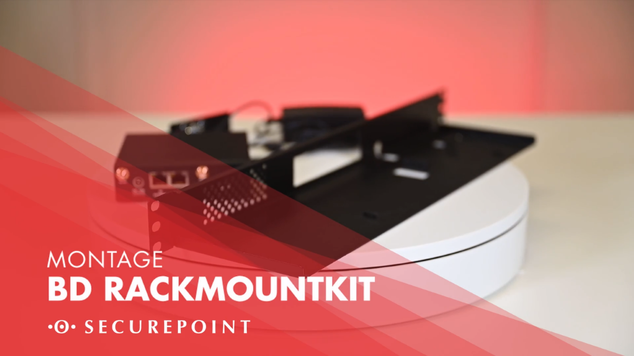

Fig.1
Step 1
- Rackmount kit for the Black Dwarf G5

Fig.2
Step 2
- Prepare cable ties for securing the power supply unit

Fig.3
Step 3
- Mount the power supply unit
- Tie up the surplus cable
- Feed the connection cable for the UTM through the prepared hole

Fig.4
Step 5
- Removed the feet of the UTM

Fig.5
Step 6
- Place the UTM and fan on the rack

Fig.6
Step 3
- Mount the fan from below using the screw.

Fig.7
Step 4
- Connect the fan to the UTM
- Tie up excess cable

Fig.8
Step 5
- Mount antennas on the UTM
- Connect the power cable to the UTM

Fig.9
Step 6
- Mount rack including UTM
RC100 Basic

Fig. 1
Step 1
- Mounting bracket for the sides

Fig. 2
Step 2
- Mounting bracket leaves ventilation outlet free

Fig. 3
Step 3
- Fasten mounting bracket laterally

Fig. 4
Step 4
- Fasten mounting bracket on the second side

Fig. 5
Step 5
- Space requirement in server rack: 1U

Fig. 6
Step 6
- Attach mounting bracket to the rack with the large silver screws
Done
RC100 Premium Kit (2024)
The instructions for the previous model (without cable ties) can be found in a archived article

Fig. 1
Step 1
- Mounting bracket left (small) and right (large)
- Patch cable
- Mounting screws
- Cable ties

Fig. 2
Step 2
- The large mounting bracket is attached to the right-hand side of the UTM with two screws

Fig. 3
Step 3
- The small mounting bracket is attached to the left-hand side of the UTM with two screws

Fig. 4
Step 4
- Connect patch cable to UTM and attach to cover ( pay attention to labelling)

Fig. 5
Step 5
- Wire all four LAN ports according to the labelling

Fig. 6
Step 6
- Secure the cables to the mount with one of the cable ties

Fig. 7
Step 7
- Prepare the cable ties for mounting the first power supply unit

Fig. 8
Step 8
- Attach the first power supply unit

Fig. 9
Step 9
- Attach the second power supply unit using the same principle

Fig. 10
Step 10
- Plug the power supply units into the UTM

Fig. 11
Step 11
- Attach power supply cable to the mount

Fig. 12
Step 12
- Compare results and correct errors if necessary

Fig. 13
Step 13
- The UTM requires 1U

Fig. 14
Step 14
- Screwing with the large silver screws
RC200 Premium Kit

Fig. 1
Step 1
- Mounting bracket left (narrow) and right (wide)

Fig. 2
Step 2
- Included LC fiber optic cable

Fig. 3
Step 3
- Included LC fiber optic cable

Fig. 4
Step 4
- Mounting bracket for 2 power supplies

Fig. 5
Step 5
- The narrow mounting bracket goes on the left side of the UTM

Fig. 6
Step 6
- Mounting with two black screws

Fig. 7
Step 7
- The wide mounting bracket with the power supply and network connections is mounted on the right side.
- Mounting also with two black screws

Fig. 8
Step 8
- Screw down the mounting bracket for the power supply units from below

Fig. 9
Step 9
- Plug in the patch cable at the back
- and fasten at the front at the correspondingly labeled opening with the silver screws
The label follows the arrangement of the status lights on the front side of the UTM

Fig. 10
Step 10
- Plug the supplied SFP module into port A4 on the UTM and plug in the supplied LC fiber cable.

Fig. 11
Step 11
- Push through the connector for the SFP port from the inside with the long end facing outward

Fig. 12
Step 12
- Fastening the connector for the LC fiber optic cable

Fig. 13
Step 13
- Insert the LC fiber optic cable into the connector

Fig. 14
Step 14
- The UTM requires 1U

Fig. 15
Step 15
- Screwing with the large silver screws
- in the picture above
RC300S
Preparation
- Screwdriver type Ph2 (not enclosed).
- Screws supplied:
- 4 small black screws (M2x4 countersunk head)
- 4 large silver screws (M5x15 flat head)
Instructions

Fig. 1
Step 1
- Mounting bracket for the sides

Fig. 2
Step 2
- Attach mounting bracket to the side

Fig. 3
Step 3
- Screws to hold the mounting brackets in the rack

Fig. 4
Step 4
- Two screws each hold the mounting brackets in the rack

Fig. 5
Step 5

RC350R - RC1000R
Preparation
- Screwdriver type Ph2 (not enclosed)
- Premium mounting rails
- From the enclosed screw sets:
- 4 thick black screws (M2x4 countersunk head)
- 6 smaller black screws (M1x2 countersunk head)
- 4 small silver-coloured screws (M4x4 flat head)
- 2 large silver-coloured screws (M5x15 flat head)
- 2 large silver-coloured screws with spacer (M5x15 flat head with shoulder)
Instructions

Fig. 1
Step 1
- Components of a mounting bracket

Fig. 2
Step 2
- Assemble the mounting brackets with the larger black screws

Fig. 3
Step 3
- Attach the mounting bracket to the enclosure with the smaller black screws

Fig. 4
Step 4
- Release the lock with the help of the small lever
- Remove the inner rail from the guide rail

Fig. 5
Step 5
- Inner rail with small fixing screws

Fig. 6
Step 6
- Mount the inner rail

Fig. 7
Step 7
- Repeat steps #01 - #06 on the other side

Fig. 8
Step 8
- Pull back the bolt of the fastening device at the end of the guide rail to hook it in

Fig. 9
Step 9
- Suspended premium guide rail

Fig. 10
Step 12
- Screws for fixing the guide rails

Fig. 11
Step 10
- Attach guide rails to the back of the rack
- Tighten screws only hand-tight

Fig. 12
Step 11
- Pull the inner rails forwards
- To hook in the units, release the lock using the small lever

Fig. 13
Step 13
- Fit the screws at the front
- Tighten only slightly

Fig. 14
Step 14