Last adaptation to the version: 14.1.0 (08.2025)
- BetaFor participants on the Beta Channel only:
- To avoid problems with NAT traversal, the Encapsulation of ESP in UDP in IKEv1 Phase1 and IKEv2 Phase1 can be enforced
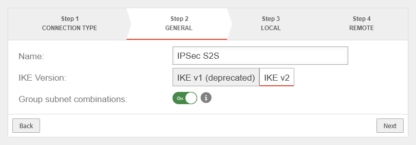
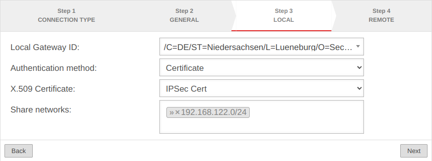
- Description of the networks to be released in Step 3 corrected
Introduction
A Site-to-Site connection links two networks together.
For example, the local network of a main office with the local network of a branch office / secondary office.
Public IP addresses, as well as dynamic DNS entries, can be used to connect the two remote gateways.
Preparation
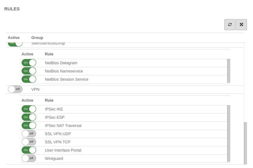
If there is a router (e.g. Fritz!Box or Speedport) in front of the Securepoint appliance, it must be ensured that ESP and UDP 500/ 4500 are active there. See Example configuration with a Fritz!Box.
Configuration of an IPSec Site-to-Site connection
After logging in to the administration interface of the firewall (in the delivery state: https://192.168.175.1:11115), an IPSec connection can be added in the menu button .
Setup Wizard
More settings
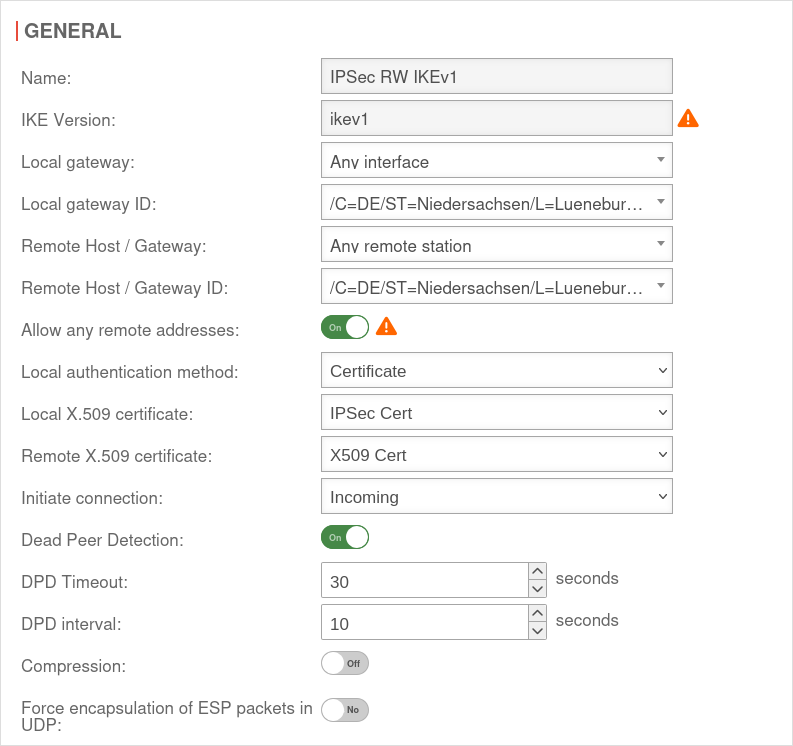
In addition to the settings that have already been defined in the wizard, further parameters can be configured:
IKEv1
| 1. | 2. | 3. |
| Abb.1 | Abb.2 | Abb.3 |
| Abbildungen | ||
Phase 1 | ||||||
Area Connections button GeneralGeneral | ||||||
| Caption | Value | Description | UTMuser@firewall.name.fqdnVPNIPSec 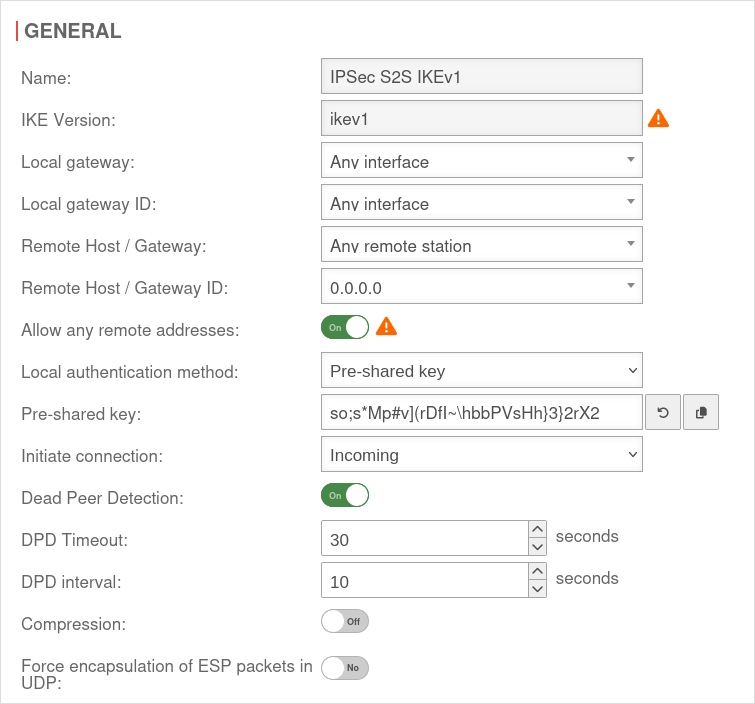 Phase 1 Genereal Phase 1 Genereal
|
|||
|---|---|---|---|---|---|---|
| Allow any remote addresses: | On Default |
Disable this option for site-to-site connections with DynDNS hosts if multiple IPsec connections with a priori unknown addresses (DynDNS S2S, Roadwarrior) are configured. | ||||
| Startup behavior: | The tunnel is initiated by the UTM even if no packets are sent. Incoming requests are accepted. | |||||
| Default if Remote Host is any | The UTM accepts incoming tunnel requests. No outgoing connection is created. | |||||
| Default if Remote Host known | The tunnel is initiated by the UTM only when packets are to be sent.notempty Only set as default value if Any remote station is not selected as Remote Host / Gateway. | |||||
| Deactivates the tunnel | ||||||
| Generate traffic: For Initiate Connection Route |
On | Prevents unwanted disconnections when no data traffic is taking place | ||||
| Dead Peer Detection: | On | Checks at a set interval whether the tunnel still exists. If the tunnel was terminated unexpectedly, the SAs are dismantled. (Only then it is also possible to reestablish a new tunnel). | ||||
| DPD Timeout: | 30 seconds | Period before the state under Startup behavior is restored. The same values are used here as for regular packets. | ||||
| DPD Interval: | 10 seconds | Testing interval | ||||
| Compression: | Off | Compression is not supported by all remote stations | ||||
| Enable MOBIKE: | Yes | Used to deactivate the MOBIKE option Deactivation prevents encrypted data from a remote station from being additionally encapsulated in 4500udp, which leads to problems in communication. | ||||
| Force encapsulation of ESP packets in UDP: notempty New as of v14.1.0 |
Off | Can prevent problems with NAT traversal negotiation (UDP encapsulation)
ipsec set id <id> flags [ “list” “existing” ‘flags’ “UDP_ENCAP” ]
| ||||
Section IKE Settings that must be identical in the UTM and in the client: IKE | ||||||
| Caption | Default UTM | Default NCP Client | 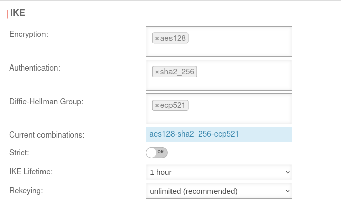 |
 | ||
| Encryption: | »aes128 | AES 128 Bit | ||||
| Authentication: | »sha2_256 | Hash: SHA2 256 Bit | ||||
| Diffie-Hellman Group: | »ecp521 | IKE DH-Gruppe: DH2 (modp1024) | ||||
| Aktuelle Kombinationen: | aes128-sha2_256-ecp521 | |||||
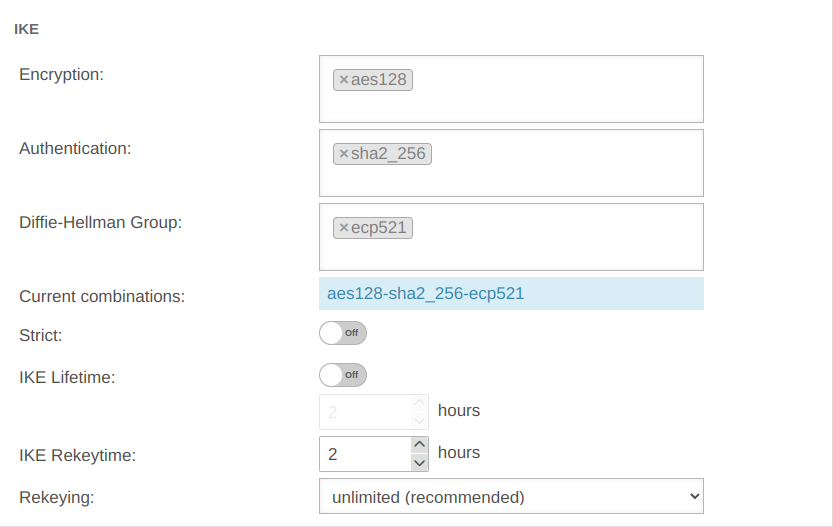
| Section IKE More settings: | ||||||
| Caption | Value | Description | ||||
| Strict: | Off | The configured parameters (authentication and encryption algorithms) are preferred for connections | ||||
| On | No further proposals are accepted. A connection is only possible with the configured parameters. | |||||
| IKE Life time: | Out 3 hours | Validity period of the Security Association: Agreement between two communicating entities in computer networks. It describes how the two parties apply security services to communicate securely with each other. When using multiple services, multiple security connections must also be established. (Source: Wikipedia 2022) in phase 1 Can be activated On in addition to IKE Rekeytime. If the Lifetime is set, the value must be greater than the Rekeytime. | ||||
| IKE Life time: | Validity period of the Security Association: Agreement between two communicating entities in computer networks. It describes how the two parties apply security services to communicate securely with each other. When using multiple services, multiple security connections must also be established. (Source: Wikipedia 2022) in phase 1 | |||||
| IKE Rekeytime: | 2 hours | The validity period in which the connection is established (initial or after termination) | ||||
| notempty Starting with version 12.5.0, for already existing' connections that have no rekeytime' set, the value of the lifetime is entered at this point and the value of the lifetime is set to 0. This significantly increases the stability of the connection and should not bring any disadvantages. If a value has already been set for the rekeytime (possible from v12.4) no change is made. Example: Current version: ike_lifetime = 2 ike_rekeytime = 0 After update: ike_lifetime = 0 ike_rekeytime = 2 ---- Current version: ike_lifetime = 2 ike_rekeytime = 1 After update: (without change) ike_lifetime =2 ike_rekeytime = 1 | ||||||
| Rekeying: | Number of attempts to establish the connection (initial or after abort). For E2S connections (Roadwarrior), the setting 3 times can avoid endless attempts to connect to devices that are not correctly logged out. | |||||
Phase 2 | ||||||
Area Connections button GeneralSection General Settings that must be identical in the UTM and in the client: | ||||||
| Caption | Default UTM | Default NCP Client | UTMuser@firewall.name.fqdnVPNIPSec 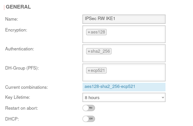 Phase 2 / Section General with / IKEv1 / Roadwarrior Phase 2 / Section General with / IKEv1 / Roadwarrior
|
UTMuser@firewall.name.fqdnVPNIPSec 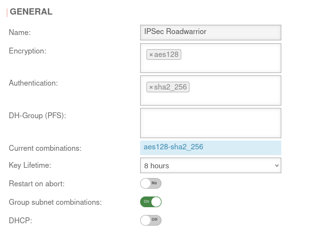 Phase 2 / Section General with / IKEv2 / Roadwarrior Phase 2 / Section General with / IKEv2 / Roadwarrior
|
UTMuser@firewall.name.fqdnVPNIPSec 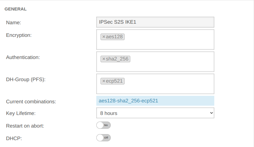 Phase 2 / Section General with / IKEv1 / S2S Phase 2 / Section General with / IKEv1 / S2S
|
UTMuser@firewall.name.fqdnVPNIPSec 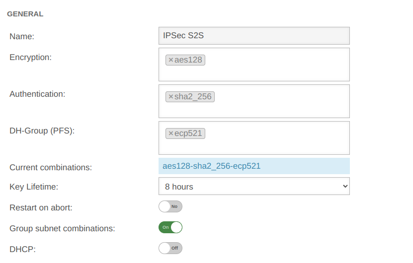 Phase 2 / Section General with / IKEv2 / S2S Phase 2 / Section General with / IKEv2 / S2S
|
| Encryption: | »aes128 | AES 128 Bit | ||||
| Authentication: | »sha2_256 | SHA2 256 Bit | ||||
| Diffie-Hellman Group: | »ecp521 | IKE DH-Gruppe: DH2 (modp1024) | ||||
| Diffie-Hellman Group: | »ecp521 | IKE DH-Gruppe: DH2 (modp1024) | ||||
| Aktuelle Kombinationen: | aes128-sha2_256-ecp521 | |||||
| Key service life: | Validity period of the key in phase 2 | |||||
| Exchange mode: | Main Mode (Not configurable) | Aggressive Mode (IKEv1) The UTM does not support Aggressive Mode for security reasons. | ||||
| Restart on abort: | No | If the connection was terminated unexpectedly, activating will restore the state configured under Startup behavior in phase 1. The Dead Peer Detection is automatically activated in phase 1.
| ||||
| DHCP: | Out | When enabled clients receive IP addresses from a local network. This requires further configurations, see wiki article on DHCP for IPSec.
| ||||
SubnetsSection Subnets | |||
| Scenario: All subnets have access to each other
With an SSH login as root, the behavior can be understood particularly well.
|
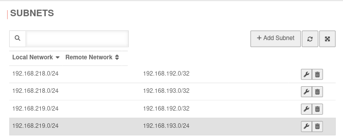 | ||
| Scenario: Not all subnets may access every network of the remote gateway
If in phase two a local network is not connected to all remote networks (or a remote network is not connected to all local ones), this will not be taken into account if the option Group subnet combinations is active! notempty The Group subnet combinations option will connect all local networks to all remote networks! Port filter rules make it possible to control access. With an SSH login as root, the behavior can be understood particularly well.
|
Datei:UTM v12.6.2 VPN Ipsec RW IKEv1 Phase 2 reduzierte Subnetze-enpng | ||
Troubleshooting
Detailed Troubleshooting instructions can be found in the Troubleshooting Guide
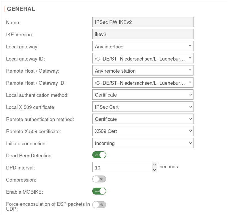
IKEv2
| 1. | 2. | 3. |
| Abb.1 | Abb.2 | Abb.3 |
| Abbildungen | ||
Phase 1 | ||||||
Area Connections button GeneralGeneral | ||||||
| Caption | Value | Description | UTMuser@firewall.name.fqdnVPNIPSec 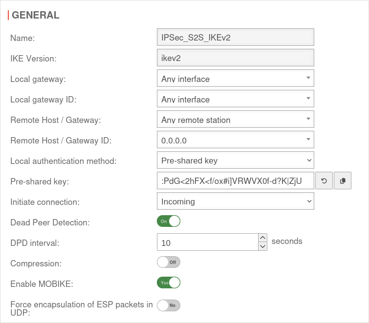 Phase 1 Genereal Phase 1 Genereal
| |||
|---|---|---|---|---|---|---|
| Startup behavior: | The tunnel is initiated by the UTM even if no packets are sent. Incoming requests are accepted. | |||||
| Default if Remote Host is any | The UTM accepts incoming tunnel requests. No outgoing connection is created. | |||||
| Default if Remote Host known | The tunnel is initiated by the UTM only when packets are to be sent.notempty Only set as default value if Any remote station is not selected as Remote Host / Gateway. | |||||
| Deactivates the tunnel | ||||||
| Generate traffic: For Initiate Connection Route |
On | Prevents unwanted disconnections when no data traffic is taking place | ||||
| Dead Peer Detection: | On | Checks at a set interval whether the tunnel still exists. If the tunnel was terminated unexpectedly, the SAs are dismantled. (Only then it is also possible to reestablish a new tunnel). | ||||
| DPD Timeout: | 30 seconds | Period before the state under Startup behavior is restored. The same values are used here as for regular packets. | ||||
| DPD Interval: | 10 seconds | Testing interval | ||||
| Compression: | Off | Compression is not supported by all remote stations | ||||
| Enable MOBIKE: | Yes | Used to deactivate the MOBIKE option Deactivation prevents encrypted data from a remote station from being additionally encapsulated in 4500udp, which leads to problems in communication. | ||||
| Force encapsulation of ESP packets in UDP: notempty New as of v14.1.0 |
Off | Can prevent problems with NAT traversal negotiation (UDP encapsulation)
ipsec set id <id> flags [ “list” “existing” ‘flags’ “UDP_ENCAP” ]
| ||||
Section IKE Settings that must be identical in the UTM and in the client: IKE | ||||||
| Caption | Default UTM | Default NCP Client |  |
 | ||
| Encryption: | »aes128 | AES 128 Bit | ||||
| Authentication: | »sha2_256 | Hash: SHA2 256 Bit | ||||
| Diffie-Hellman Group: | »ecp521 | IKE DH-Gruppe: DH2 (modp1024) | ||||
| Aktuelle Kombinationen: | aes128-sha2_256-ecp521 | |||||
| Section IKE More settings: | ||||||
| Caption | Value | Description | ||||
| Strict: | Off | The configured parameters (authentication and encryption algorithms) are preferred for connections | ||||
| On | No further proposals are accepted. A connection is only possible with the configured parameters. | |||||
| IKE Life time: | Out 3 hours | Validity period of the Security Association: Agreement between two communicating entities in computer networks. It describes how the two parties apply security services to communicate securely with each other. When using multiple services, multiple security connections must also be established. (Source: Wikipedia 2022) in phase 1 Can be activated On in addition to IKE Rekeytime. If the Lifetime is set, the value must be greater than the Rekeytime. | ||||
| IKE Life time: | Validity period of the Security Association: Agreement between two communicating entities in computer networks. It describes how the two parties apply security services to communicate securely with each other. When using multiple services, multiple security connections must also be established. (Source: Wikipedia 2022) in phase 1 | |||||
| IKE Rekeytime: | 2 hours | The validity period in which the connection is established (initial or after termination) | ||||
| notempty Starting with version 12.5.0, for already existing' connections that have no rekeytime' set, the value of the lifetime is entered at this point and the value of the lifetime is set to 0. This significantly increases the stability of the connection and should not bring any disadvantages. If a value has already been set for the rekeytime (possible from v12.4) no change is made. Example: Current version: ike_lifetime = 2 ike_rekeytime = 0 After update: ike_lifetime = 0 ike_rekeytime = 2 ---- Current version: ike_lifetime = 2 ike_rekeytime = 1 After update: (without change) ike_lifetime =2 ike_rekeytime = 1 | ||||||
| Rekeying: | Number of attempts to establish the connection (initial or after abort). For E2S connections (Roadwarrior), the setting 3 times can avoid endless attempts to connect to devices that are not correctly logged out. | |||||
Phase 2 | ||||||
Area Connections button GeneralSection General Settings that must be identical in the UTM and in the client: | ||||||
| Caption | Default UTM | Default NCP Client | UTMuser@firewall.name.fqdnVPNIPSec  Phase 2 / Section General with / IKEv1 / Roadwarrior Phase 2 / Section General with / IKEv1 / Roadwarrior
|
UTMuser@firewall.name.fqdnVPNIPSec  Phase 2 / Section General with / IKEv2 / Roadwarrior Phase 2 / Section General with / IKEv2 / Roadwarrior
|
UTMuser@firewall.name.fqdnVPNIPSec  Phase 2 / Section General with / IKEv1 / S2S Phase 2 / Section General with / IKEv1 / S2S
|
UTMuser@firewall.name.fqdnVPNIPSec  Phase 2 / Section General with / IKEv2 / S2S Phase 2 / Section General with / IKEv2 / S2S
|
| Encryption: | »aes128 | AES 128 Bit | ||||
| Authentication: | »sha2_256 | SHA2 256 Bit | ||||
| Diffie-Hellman Group: | »ecp521 | IKE DH-Gruppe: DH2 (modp1024) | ||||
| Diffie-Hellman Group: | »ecp521 | IKE DH-Gruppe: DH2 (modp1024) | ||||
| Aktuelle Kombinationen: | aes128-sha2_256-ecp521 | |||||
| Key service life: | Validity period of the key in phase 2 | |||||
| Exchange mode: | Main Mode (Not configurable) | Aggressive Mode (IKEv1) The UTM does not support Aggressive Mode for security reasons. | ||||
| Restart on abort: | No | If the connection was terminated unexpectedly, activating will restore the state configured under Startup behavior in phase 1. The Dead Peer Detection is automatically activated in phase 1.
| ||||
| Group subnet combinations: | Yes |
If more than one network is configured on the local side or at the remote gateway, a separate SA is negotiated for each subnet combination when it is deactivated. This results in numerous subnet combinations and thus many SAs, especially with multiple subnets, and leads to limitations and losses in the stability of the connections due to the design of the IPSec protocol. | ||||
| DHCP: | Out | When enabled clients receive IP addresses from a local network. This requires further configurations, see wiki article on DHCP for IPSec.
| ||||
SubnetsSection Subnets | |||
| Scenario: All subnets have access to each other
With an SSH login as root, the behavior can be understood particularly well.
|
 | ||
| Scenario: Not all subnets may access every network of the remote gateway
If in phase two a local network is not connected to all remote networks (or a remote network is not connected to all local ones), this will not be taken into account if the option Group subnet combinations is active! notempty The Group subnet combinations option will connect all local networks to all remote networks! Port filter rules make it possible to control access. With an SSH login as root, the behavior can be understood particularly well.
|
Datei:UTM v12.6.2 VPN Ipsec RW IKEv1 Phase 2 reduzierte Subnetze-enpng | ||
Troubleshooting
Detailed Troubleshooting instructions can be found in the Troubleshooting Guide
Rulebook
To grant access to the internal network, the connection must be allowed.
Configuration of the second gateway
Use of a Securepoint UTM
On the remote gateway, the settings must be made in a similar way
- A new IPSec VPN connection is created using the IPSec wizard
- A network object for the IPSec network is created
- Port filter rules are created
Remote Gateway step 2
- The same authentication method must be selected
- The same authentication key (PSK, certificate, RSA key) must be available
- The same IKE version must be used
Remote Gateway step 3
- As Local Gateway ID the Remote Gateway ID from step 4 of the first UTM must now be used
- Under Share Networks the (there remote) network from step 4 of the first UTM must also be used
Remote Gateway step 4
- The public IP address (or a hostname that can be resolved via DNS) of the first UTM must be entered as Remote Gateway.
(This address was not required in the wizard of the first UTM). - The Local Gateway ID from step 3 of the first UTM must be used as Remote Gateway ID
- Under Share networks the (there local) network from step 3 of the first UTM must also be used.
Create network object of the remote gateway
- The network object of the remote gateway represents the network of the first UTM.
Correspondingly, the network address of the local network of the first UTM must be entered under Address.
In the example 192.168.218.0/24
Notes
The transparent HTTP proxy
If a server behind the Site-to-Site connection is to be accessed from the internal network via HTTP, the transparent HTTP proxy may filter the packets.
This can lead to errors while accessing the target.
To prevent this from happening, a rule Exclude must be created in the Area Transparent mode button menu with source internal-network to target name-vpn-network-object and protocol HTTP.
Troubleshooting
Detailed Troubleshooting instructions can be found in the Troubleshooting Guide
Connection Rate Limit
Throttling of access from certain source IPs to recurring ports
notempty
The function can initially only be configured via the CLI
SSL-VPN accesses can be protected against aggressive scans or login attempts, for example.
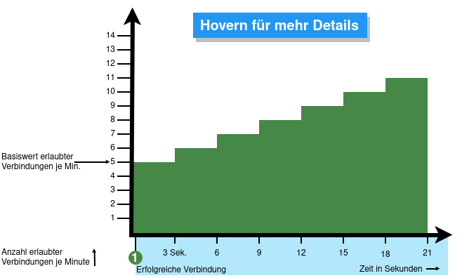
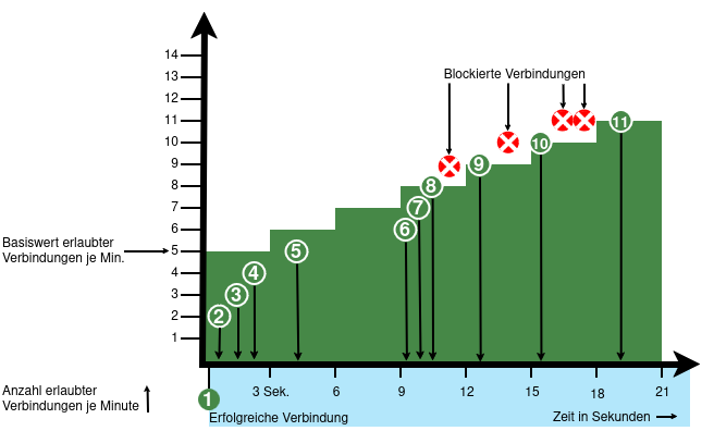
From v12.6.2, the UTM can limit the number of TCP and/or UDP connections from an external IP address to one port.
The following conditions apply:
- Only incoming connections for which a default route exists are monitored
- The connections from an IP address to a port of the UTM are counted within one minute
- When activated, 5 connections / connection attempts per minute are permitted.
The connections are then limited:- The additionally permitted connections are distributed evenly within 60 seconds of the first connection.
- With a CONNECTION_RATE_LIMIT value of 20, an additional connection is added every 3 seconds.
- 10 seconds after the first login, 3 further connections could be established (each from the same IP address to the same destination port)
- Blocking an IP address only affects access to the port that has been used too often.
Other ports can still be accessed.
- The function is activated by default for new installations on 20 UDP connections / minute on all ports
- For Updates the function must be manually activated
| extc-Variable | Default | Description |
|---|---|---|
| CONNECTION_RATE_LIMIT_TCP | 0 | Number of permitted TCP connections of an IP address per port 0 = Function deactivated, no blocking is performed |
| CONNECTION_RATE_LIMIT_TCP_PORTS | Ports to be monitored. Empty by default=all ports would be monitored (if activated). Individual ports are separated by spaces: [ 1194 1195 ] | |
| CONNECTION_RATE_LIMIT_UDP | 20 / 0 Default setting for new installations from v12.6.2: 20 For update installations the value is 0, so the function is deactivated. |
Number of permitted UDP connections of an IP address per port |
| CONNECTION_RATE_LIMIT_UDP_PORTS | Ports to be monitored. Empty by default=all ports are monitored (only for new installations!). Individual ports are separated by spaces: [ 1194 1195 ] |
Configuration with CLI commands
| CLI command | Function |
|---|---|
| extc value get application securepoint_firewall Alternatively as root user: spcli extc value get application securepoint_firewall | grep RATE |
Lists all variables of the securepoint_firewall application. The variables beginning with CONNECTION_RATE_LIMIT_ are responsible for the connection limit. application |variable |value --------------------+-------------------------------+----- securepoint_firewall |… |… |CONNECTION_RATE_LIMIT_TCP |0 |CONNECTION_RATE_LIMIT_TCP_PORTS| |CONNECTION_RATE_LIMIT_UDP |20 |CONNECTION_RATE_LIMIT_UDP_PORTS| |
| extc value set application securepoint_firewall variable CONNECTION_RATE_LIMIT_TCP value 20 system update rule |
Limits the allowed number of TCP connections from a single IP address to a specific port to 20 per minute
A change is made directly by a rule update. The value must not be set to 0 first! |
| extc value set application securepoint_firewall variable CONNECTION_RATE_LIMIT_TCP value 0 system update rule |
Deactivates the monitoring of TCP connections |
| extc value set application securepoint_firewall variable CONNECTION_RATE_LIMIT_TCP_PORTS value [ 443 11115 ] system update rule |
Restricts the monitoring of TCP connections to ports 443 and 11115 There must be spaces before and after the square brackets [ ]! |
| extc value set application securepoint_firewall variable CONNECTION_RATE_LIMIT_TCP_PORTS value [ ] system update rule |
There must be spaces before and after the square brackets [ ]! |
| extc value set application securepoint_firewall variable CONNECTION_RATE_LIMIT_UDP value 20 system update rule |
Limits the allowed number of UDP connections from a single IP address to a specific port to 20 per minute Default setting for new installations from v12.6.2: 20 For update installations the value is 0, so the function is deactivated. The value must not be set to 0 first! |
| extc value set application securepoint_firewall variable CONNECTION_RATE_LIMIT_UDP value 0 system update rule |
Deactivates the monitoring of UDP connections |
| extc value set application securepoint_firewall variable CONNECTION_RATE_LIMIT_UDP_PORTS value [ 1194 1195 ] system update rule |
Restricts the monitoring of UDP connections to ports 1194 and 1195. (Example for 2 created SSL-VPN tunnels). There must be spaces before and after the square brackets [ ]! |
| extc value set application securepoint_firewall variable CONNECTION_RATE_LIMIT_UDP_PORTS value [ ] system update rule |
There must be spaces before and after the square brackets [ ]! |
extc value set application securepoint_firewall variable CONNECTION_RATE_LIMIT_TCP value 20 notempty Finally, the CLI command system update rule must be entered so that the values in the rules are applied. |
For example, to allow a maximum of 20 connections per minute per IP address and port. For TCP, monitoring is restricted to ports 443 and 11115. All ports are monitored for UDP connections. |


