


Example scenarios for VoIP configuration with the Securepoint UTM
New article: 09.2025
notempty
This article refers to a Beta version
-
Vorbemerkung
FAQs for troubleshooting and, for example, other protocol options (UDP without SIP Helper, TCP with SIP Helpers) can be found in a separate article.
Router with integrated telephone system
Example scenario 1: Router with integrated telephone system

- The router (e.g., Fritz!Box) requires a route to the networks behind the firewall Show route creation on the Fritz!BoxHide ExampleKlicken für dauerhafte AnzeigeNote
This article includes descriptions of third-party software and is based on the status at the time this page was created.
Changes to the user interface on the part of the manufacturer are possible at any time and must be taken into account accordingly in the implementation.
All information without warranty.- Szenario:
- IP address of the Fritz!Box in the internal network: 192.168.178.1
- IP address of the UTM in the network to the Fritz!Box (e.g., A0, Zone external): 192.168.178.2
- Network IP of the internal network where the VoIP clients are located (e.g., A1, Zone internal-network): 192.168.175.0/24
- Example Fritz!Box:
- Menu Homenetwork → Network→ Tab Networksettings → Option Advanced Settings → Section Static Routes Table → Button
- Button
- IPv4-Network: 192.168.175.0
- Subnetmask: 255.255.255.0
- Gateway: 192.168.178.1
- Checkbox: IPv4 Route Active
- Button Apply
Show route creation on the SpeedportHide ExampleKlicken für dauerhafte AnzeigeNote
This section includes descriptions of third-party software and is based on the status at the time this page was created.
Changes to the user interface on the part of the manufacturer are possible at any time and must be taken into account accordingly in the implementation.
All information without warranty.- Szenario:
- The internal network IP address of the Speedport is 192.168.2.1
- UTM IP address in the Speedport network (e.g., A0, Zone "external"): 192.168.2.2
- Network IP of the internal network where the VoIP clients are located (e.g., A1, Zone "internal-network"): 192.168.175.0/24
- Example for Speedport:
- Menu Home Network → Network Settings → Routing
(The path may vary slightly depending on the model, e.g., "Advanced Settings → Static Routes") - Add a new route:
- Destination network: 192.168.175.0
- Subnetmask: 255.255.255.0
- Gateway: 192.168.2.1
- Interface:LAN
- Button Apply
- Menu Home Network → Network Settings → Routing
- Szenario:
- A network object for the router is created in the packet filter.
- A rule group is created and placed as high as possible in the rule set. If available, recreate auto-generated rules in another group and then disable them.
UTMuser@firewall.name.fqdnFirewallNetwork objects 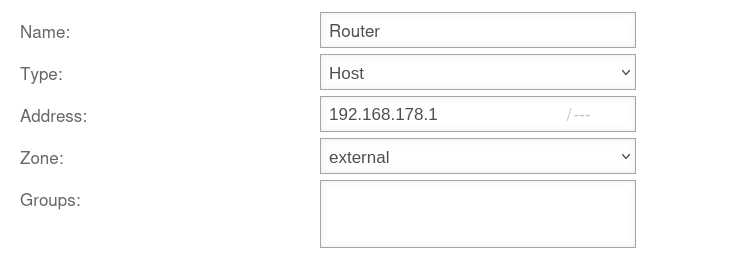

Fig.1
- Create a network object for the router under button
UTMuser@firewall.name.fqdnFirewallPacket filter 

Fig.2
A rule group for the packet filter rules should be created under button .
Move this group to the top position
UTMuser@firewall.name.fqdnFirewallPacket filter 

Fig.3
- Create an outgoing packet filter rule under button .
- Assign the rule to the previously created group so that it is executed before other rules
UTMuser@firewall.name.fqdnFirewallPacket filter 

Fig.4
- Create an incoming packet filter rule under button
- Assign the rule to the previously created group so that it is executed before other rules
Overview of rules
| # | Source | Target | Service | NAT | Logging | Action | Active | ||||
| 1 | HNE | 3/Min |
ACCEPT | On | (Fig.3) | ||||||
| 2 | 3/Min |
ACCEPT | On | (Fig.4) |
Telephone system and UTM in the same network on a router
Example scenario 2: Telephone system and UTM in the same network on a router

notempty
This configuration should be avoided if possible! If no routes can be stored in the telephone system, asynchronous routing is very likely to occur.
The telephone system should ideally be set up in its own network behind the firewall. Then Example scenario 3 applies.
The telephone system should ideally be set up in its own network behind the firewall. Then Example scenario 3 applies.
With rules on the telephone system
Example scenario 2a: With rules on the telephone system
UTMuser@firewall.name.fqdnFirewallNetwork objects 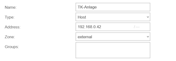

Fig.1
- A network object for the telephone system must be created under button
UTMuser@firewall.name.fqdnFirewallPacket filter
Fig.2
A rule group for the packet filter rules should be created under button .
Move this group to the top position
UTMuser@firewall.name.fqdnFirewallPacket filter 

Fig.3
- Create an outgoing packet filter rule under button .
- Assign the rule to the previously created group so that it is executed before other rules
UTMuser@firewall.name.fqdnFirewallPacket filter 

Fig.4
- Create an incoming packet filter rule under button .
- Assign the rule to the previously created group so that it is executed before other rules
Overview of rules
| # | Source | Target | Service | NAT | Logging | Action | Active | ||||
| 2 | HNE | 3/Min |
ACCEPT | On | (Fig.3) | ||||||
| 4 | 3/Min |
ACCEPT | On | (Fig.4) |
Without rules on the telephone system
Example scenario 2b: Without rules on the telephone system
If no rules can be created on the telephone system, rules for communication with the router must also be created on the UTM. This requires creating a network object for the router and two rules. In total, the following rules must be created in this scenario:
| # | Source | Target | Service | NAT | Logging | Action | Active | ||||
| 1 | HNE | 3/Min |
ACCEPT | On | (Fig.3) | ||||||
| 2 | HNE | 3/Min |
ACCEPT | On | (Fig.3) | ||||||
| 3 | 3/Min |
ACCEPT | On | (Fig.4) | |||||||
| 4 | 3/Min |
ACCEPT | On | (Fig.4) |
Telephone system in its own network on the UTM with router
Example scenario 3: Telephone system in its own network on the UTM with router

- A rule group is created and placed as high as possible in the rule set. If available
- if necessary, a separate rule for the SIP protocol can be omitted if SIP is transmitted encrypted (this may be required by the provider and must then be set up on the telephone system)
- Recreate auto-generated rules in another group and then disable them
- Note: Double NAT occurs here: once through the UTM and once through the router!
UTMuser@firewall.name.fqdnFirewallNetwork objects 

Fig.1
- A network object for the telephone system must be created under button
UTMuser@firewall.name.fqdnFirewallPacket filter
Fig.2
A rule group for the packet filter rules should be created under button .
Move this group to the top position
UTMuser@firewall.name.fqdnFirewallPacket filter 

Fig.3
An outgoing packet filter rule with the service  any must be created under button .
Assign the rule to the previously created group so that it is executed before other rules
UTMuser@firewall.name.fqdnFirewallPacket filter 

Fig.4
- Wenn SIP verschlüsselt arbeitet, ist diese Regel nicht notwendig.
- An outgoing packet filter rule with the service
 sip must be created under button
 - Assign the rule to the previously created group so that it is executed before other rules
Overview of rules
| # | Source | Target | Service | NAT | Logging | Action | Active | ||||
| 2 | HN | 3/Min |
ACCEPT | On | (Fig.3) | ||||||
| 1 | HN | 3/Min |
ACCEPT | On | (Fig.4) |
Telephone system in its own network on the UTM / direct internet access
Example scenario 4: Telephone system in its own network on the UTM / direct internet access

- In this configuration, the Conntrack modules should not be used via port filter rules.
- In most cases, it is important that a STUN server is configured in the telephone system, or, as with Starface, the external IP (can be checked under Server → Network) is determined in another way. Usually, the telephone system must also be made to set this IP in the SDP part of the SIP packet.
With Starface, this works in the connection profile. There is a NAT setting there. - If the provider does not offer a STUN server, it usually works without one. However, this cannot be relied upon.
UTMuser@firewall.name.fqdnFirewallNetwork objects
Fig.1
- A network object for the telephone system must be created under button
UTMuser@firewall.name.fqdnFirewallPacket filter
Fig.2
A rule group for the packet filter rules should be created under button .
Move this group to the top position
UTMuser@firewall.name.fqdnFirewallPacket filter If SIP operates encrypted or via TCP, this rule is not necessary.
Fig.3
- An outgoing packet filter rule with the service sip must be created under button
- Assign the rule to the previously created group so that it is executed before other rules
UTMuser@firewall.name.fqdnFirewallPacket filter
Fig.4
- An outgoing packet filter rule with the service
- Assign the rule to the previously created group so that it is executed before other rules
Overview of rules
| # | Source | Target | Service | NAT | Logging | Action | Active | ||||
| 1 | HN | 3/Min |
ACCEPT | On | (Fig.3) | ||||||
| 2 | HN | 3/Min |
ACCEPT | On | (Fig.4) |